Comparison of Schedule Managing Methods
(→Implementation example of the described methods) |
|||
| (11 intermediate revisions by one user not shown) | |||
| Line 1: | Line 1: | ||
| + | ''Developed by Mathias Ekström Larsen'' | ||
| + | |||
| + | |||
Projects involve many different tasks that must be done to complete the project. Many of these tasks will in construction projects logically depend on each other. For example, it is necessary to build supporting walls or columns before the roof can be installed. There are several methods to keep track of these dependencies. In this article, similar methods will be explained and their differences will be compared together with their advantages and disadvantages. The life cycle of construction projects can overall be split into two groups. Either the project will be planned and managed with a sequential life cycle or an adaptive life cycle. The main difference between the two are that the sequential life cycle has a number of tasks that depends on each other and are planned very early in the project. It is difficult to change the plan as the project progresses which makes it vulnerable to delays. The adaptive life cycle on the other hand makes a rough plan with the overall tasks in the beginning of the project. The detailed planning of the individual tasks is then done as the project progresses. This way of planning is therefore less vulnerable to delays. | Projects involve many different tasks that must be done to complete the project. Many of these tasks will in construction projects logically depend on each other. For example, it is necessary to build supporting walls or columns before the roof can be installed. There are several methods to keep track of these dependencies. In this article, similar methods will be explained and their differences will be compared together with their advantages and disadvantages. The life cycle of construction projects can overall be split into two groups. Either the project will be planned and managed with a sequential life cycle or an adaptive life cycle. The main difference between the two are that the sequential life cycle has a number of tasks that depends on each other and are planned very early in the project. It is difficult to change the plan as the project progresses which makes it vulnerable to delays. The adaptive life cycle on the other hand makes a rough plan with the overall tasks in the beginning of the project. The detailed planning of the individual tasks is then done as the project progresses. This way of planning is therefore less vulnerable to delays. | ||
| Line 17: | Line 20: | ||
=====The critical chain method===== | =====The critical chain method===== | ||
| − | The critical path method does not take resources into account when calculating the shortest execution time. The resources in a construction project are categorized in three types. Plant which consists of equipment such as cranes or piling rigs which can not be in more than one place at a time, labour which also can not be in two places at a time and space for the work to be executed in. For the first two types of resources, the critical chain method can be used. The critical chain in the project is calculated similarly to the critical path method however this method calculates the longest resource-constrained path. The uncertainty is also handled differently from the critical path method. Instead of having buffers in each of the individual tasks, the estimated time is assumed to be the average duration for such a task. The critical chain then gets a project buffer at the end while the remaining paths gets feeder buffers. For further description of the critical chain method, see <span class="plainlinks">[http://apppm.man.dtu.dk/index.php/Critical_Chain_Theory Critical Chain Theory]</span>. | + | The critical path method does not take resources into account when calculating the shortest execution time. The resources in a construction project are categorized in three types. Plant which consists of equipment such as cranes or piling rigs which can not be in more than one place at a time, labour which also can not be in two places at a time and space for the work to be executed in. For the first two types of resources, the critical chain method can be used. The critical chain in the project is calculated similarly to the critical path method however this method calculates the longest resource-constrained path. The uncertainty is also handled differently from the critical path method. Instead of having buffers in each of the individual tasks, the estimated time is assumed to be the average duration for such a task. The critical chain then gets a project buffer at the end while the remaining paths gets feeder buffers. This also moves the responsibility of task completion on time from the task managers to the project manager. Parkinson's law which states "work expands so as to fill the time available for its completion"<ref name=Winch /> is reduced by moving the responsibility and reducing the task durations. The total project life time will therefore be reduced by reducing the effect of Parkinson's law. For further description of the critical chain method, see <span class="plainlinks">[http://apppm.man.dtu.dk/index.php/Critical_Chain_Theory Critical Chain Theory]</span>. |
[[File:CCM Winch.PNG|350px|thumb|center|Figure 2: Visualization of the critical chain method. <ref name=Winch />]] | [[File:CCM Winch.PNG|350px|thumb|center|Figure 2: Visualization of the critical chain method. <ref name=Winch />]] | ||
| Line 36: | Line 39: | ||
=====The dependency structure matrix===== | =====The dependency structure matrix===== | ||
| − | + | A way to make a plan for an adaptive life cycle is to make a dependency structure matrix (DSM). The dependency structure matrix consists of all design tasks in a matrix form in both rows and columns. The way the matrix works is that all tasks that depends on information from other tasks gets the box filled in. The matrix will then have a filled diagonal which simply shows that each task depends on itself. All the filled boxes below the diagonal is not a problem as they will have the required information in time since the depending tasks will be finished before the start of the relevant task. The filled boxes above the diagonal, however, depends on information from tasks that starts later. The way to handle such tasks is to either estimate the required information or simply delay the completion of the tasks <ref name=Winch>Winch, Graham (2010), "Managing Construction Projects. An Information Processing Approach" Second Edition, Wiley-Blackwell, United Kingdom. ISBN 978-1-4051-8457-1.</ref>. The amount of such tasks can be reduced by moving the tasks around in the matrix such that the dependencies gets below or close the diagonal. The dependency structure matrix can for example be used in the design phase as an iterative tool where the architect sends a structure design to the engineer who then sends some suggested changes back to the architect and so on. A more in-depth explanation of the dependency structure matrix can be seen in <span class="plainlinks">[http://apppm.man.dtu.dk/index.php/Application_of_Dependency_Structure_Matrix_in_Time_Scheduling Application of Dependency Structure Matrix in Time Scheduling]</span> | |
| − | + | [[File:Design Structure Matrix.png|250px|thumb|center|Figure 5: Example of a dependency structure matrix. <ref name=DSM_wiki>"Design structure matrix". Retrieved June 19, 2017, from https://en.wikipedia.org/wiki/Design_structure_matrix.</ref>]] | |
<div style="clear:both;"></div> | <div style="clear:both;"></div> | ||
| Line 54: | Line 57: | ||
[[File:DSM example.PNG|250px|thumb|center|Figure 8: Dependency structure matrix for the example.]] | [[File:DSM example.PNG|250px|thumb|center|Figure 8: Dependency structure matrix for the example.]] | ||
It can be seen in figure 8 that the dependency structure matrix for the current example shows no dependency problems as all the dependencies are situated below the diagonal. This also means that no further optimization of the matrix is needed. For the sake of illustrating the dependency structure matrix, a change in the dependencies is made such that task H now depends on the completion of task I. | It can be seen in figure 8 that the dependency structure matrix for the current example shows no dependency problems as all the dependencies are situated below the diagonal. This also means that no further optimization of the matrix is needed. For the sake of illustrating the dependency structure matrix, a change in the dependencies is made such that task H now depends on the completion of task I. | ||
| − | [[File:DSM example ALT.PNG|550px|thumb|center|Figure 9: Dependency structure matrix for an | + | [[File:DSM example ALT.PNG|550px|thumb|center|Figure 9: Dependency structure matrix for an alternative example. Left figure has a dependency problem marked with red which is solved in the right figure]] |
In the left matrix in figure 9, it can be seen that there now is a dependency above the diagonal. If these tasks are in the design phase, two approaches can be made to accommodate this problem. Either the result from task I can be estimated and then feed the estimate into task H. Otherwise task I has to complete before task H can begin. In this case, it is possible to switch the places of task H and I which can solve this problem. This is illustrated in the right matrix in figure 9. This change in the order of task execution, however, also changes the critical path. This new critical path can be seen in figure 10. | In the left matrix in figure 9, it can be seen that there now is a dependency above the diagonal. If these tasks are in the design phase, two approaches can be made to accommodate this problem. Either the result from task I can be estimated and then feed the estimate into task H. Otherwise task I has to complete before task H can begin. In this case, it is possible to switch the places of task H and I which can solve this problem. This is illustrated in the right matrix in figure 9. This change in the order of task execution, however, also changes the critical path. This new critical path can be seen in figure 10. | ||
[[File:Critical path example ALT.png|350px|thumb|center|Figure 10: The critical path method for the alternative example.]] | [[File:Critical path example ALT.png|350px|thumb|center|Figure 10: The critical path method for the alternative example.]] | ||
| Line 65: | Line 68: | ||
=Advantages and limitations= | =Advantages and limitations= | ||
| − | '''The sequential life cycle methods''' generally consist of strategical tools which means that they make an overall plan of a project. It is usually an advantage to make such a plan as the total project time most likely would be longer without an idea of | + | '''The sequential life cycle methods''' generally consist of strategical tools which means that they make an overall plan of a project. It is usually an advantage to make such a plan, as the total project time most likely would be longer without an idea of which tasks should be done at a given time. The sequential methods, however, are not very robust when it comes to delays. A delay in a task can result in delay of the entire project in which case the plan would have to be re-evaluated. A delay in one task can also result in further delays in other tasks that depends on the completion of the delayed task. |
'''The adaptive life cycle methods''' generally consist of tactical tools which means that they go into the detailed planning throughout the project. This makes projects less vulnerable to delays as the work in each task more easily can be rescheduled as the project goes on. The adaptive methods do, however, not work without an overall plan such as the sequential methods. | '''The adaptive life cycle methods''' generally consist of tactical tools which means that they go into the detailed planning throughout the project. This makes projects less vulnerable to delays as the work in each task more easily can be rescheduled as the project goes on. The adaptive methods do, however, not work without an overall plan such as the sequential methods. | ||
| − | Each method in both the sequential and adaptive life cycles have their own advantages as well as disadvantages. A list of | + | Each method in both the sequential and adaptive life cycles have their own advantages as well as disadvantages. A list of the key points can be seen below. |
* '''The critical path method''' | * '''The critical path method''' | ||
** ''Advantages'' | ** ''Advantages'' | ||
| − | *** It gives an estimate of the duration of the project as well as individual tasks throughout the project life | + | *** It gives an estimate of the duration of the project as well as individual tasks throughout the project life. |
| − | *** It is a simple method for small projects | + | *** It is a simple method for small projects. |
** ''Disadvantages'' | ** ''Disadvantages'' | ||
| − | *** It does not take resources into account | + | *** It does not take resources into account. |
*** It is difficult to maintain the schedule in case of changes or delays in tasks. | *** It is difficult to maintain the schedule in case of changes or delays in tasks. | ||
*** Uncertainty is not taken care of by the method. | *** Uncertainty is not taken care of by the method. | ||
| Line 94: | Line 97: | ||
** ''Disadvantages'' | ** ''Disadvantages'' | ||
*** The project has to be planned in detail at a relatively early stage in the project. | *** The project has to be planned in detail at a relatively early stage in the project. | ||
| − | *** It is difficult to change the plan which makes it vulnerable to changes and delays. | + | *** It is difficult to change the plan, which makes it vulnerable to changes and delays. |
* '''Last planner method''' | * '''Last planner method''' | ||
** ''Advantages'' | ** ''Advantages'' | ||
| − | *** Inclusion of the workers in the planning process | + | *** Inclusion of the workers in the planning process. |
| − | *** Important decisions of the detailed planning are made later in the project when more | + | *** Important decisions of the detailed planning are made later in the project when more information about the project is known. |
*** Robust against changes and delays since the detailed planning is done continuously. | *** Robust against changes and delays since the detailed planning is done continuously. | ||
** ''Disadvantages'' | ** ''Disadvantages'' | ||
Latest revision as of 12:41, 19 November 2018
Developed by Mathias Ekström Larsen
Projects involve many different tasks that must be done to complete the project. Many of these tasks will in construction projects logically depend on each other. For example, it is necessary to build supporting walls or columns before the roof can be installed. There are several methods to keep track of these dependencies. In this article, similar methods will be explained and their differences will be compared together with their advantages and disadvantages. The life cycle of construction projects can overall be split into two groups. Either the project will be planned and managed with a sequential life cycle or an adaptive life cycle. The main difference between the two are that the sequential life cycle has a number of tasks that depends on each other and are planned very early in the project. It is difficult to change the plan as the project progresses which makes it vulnerable to delays. The adaptive life cycle on the other hand makes a rough plan with the overall tasks in the beginning of the project. The detailed planning of the individual tasks is then done as the project progresses. This way of planning is therefore less vulnerable to delays.
Contents |
[edit] Description of different schedule managing methods
When it comes to schedule managing methods in construction there are two overall ways the project life cycle is manged. These are sequential life cycle and adaptive life cycle.
[edit] The sequential life cycle
The sequential life cycle is the most traditional way of managing construction projects whereas the adaptive methods has not been used as much. The main idea of the sequential life cycle is that the entire project is planned early in the project. The plan consists of different phases which have specified ending criteria which have to be met before the successor phase can begin. This also means that the entire project has to be well known [1]. Since the entire project is planned in the early stages of the project, this way of planning is vulnerable to unforeseen changes which could have huge effects on the upcoming phases. There are several ways of conducting a sequential life cycle such as the critical path method, the critical chain method, the limited space analysis (LSA) and Location-based Scheduling (LSB).
[edit] The critical path method
The critical path method works by dividing a project into smaller tasks. The duration for these tasks are estimated by either comparing similar tasks in earlier projects or by asking those who are in charge of the specific task. These duration estimates naturally have some amount of uncertainty; however, this uncertainty is not considered in the critical path method. This uncertainty either must be accepted or considered externally with the use of probabilistic methods. A probabilistic method that can be used to estimate these uncertainties is the Program Review and Evaluation Technique (PERT). PERT estimates the task durations based on three values. The most likely duration, a pessimistic duration and an optimistic duration. These values are then used to calculate the expected duration by a beta distribution. A more in-depth description about PERT can be seen in PERT/CPM. When the tasks are defined and the durations are specified, the tasks can be put into a schedule. The schedule is made so that tasks that needs other tasks to finish beforehand are put in a path. The longest duration of the paths then defines the critical path and thereby the shortest execution time of the project. For further description of the critical path method, see The Critical Path Method in project planning.
[edit] The critical chain method
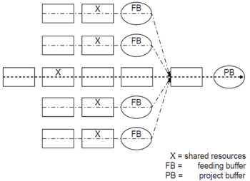
The critical path method does not take resources into account when calculating the shortest execution time. The resources in a construction project are categorized in three types. Plant which consists of equipment such as cranes or piling rigs which can not be in more than one place at a time, labour which also can not be in two places at a time and space for the work to be executed in. For the first two types of resources, the critical chain method can be used. The critical chain in the project is calculated similarly to the critical path method however this method calculates the longest resource-constrained path. The uncertainty is also handled differently from the critical path method. Instead of having buffers in each of the individual tasks, the estimated time is assumed to be the average duration for such a task. The critical chain then gets a project buffer at the end while the remaining paths gets feeder buffers. This also moves the responsibility of task completion on time from the task managers to the project manager. Parkinson's law which states "work expands so as to fill the time available for its completion"[2] is reduced by moving the responsibility and reducing the task durations. The total project life time will therefore be reduced by reducing the effect of Parkinson's law. For further description of the critical chain method, see Critical Chain Theory.
[edit] The critical space analysis and location based scheduling
In small construction sites with limited space, the workers may not be able to work effectively simultaneously. The critical space analysis addresses this issue by using the available space as a resource similarly to the critical chain method. The fastest execution time of the project then depends on reduced effectiveness of the work. The location based scheduling (LBS) focuses primarily on the work flow of activities that share the same space. This is done by first displaying all the activities in a way that shows the locations of the activities at any given time. Overlapping activities are then organized so that they do not interfere with each other. The activities are then connected to form continuous work flows. When this is done, it can be considered to balance the resources by adding additional resources to activities that delays the start of other activities as well as reducing resources for activities that does not have to finish as fast. An illustration of a location based schedule can be seen in figure 3 where location conflicts are marked with the red squares. By optimizing the work flow and reallocating resources between the tasks, an optimized schedule can be made as shown in figure 4. For further description of location based scheduling, see Location Based Scheduling.


[edit] The adaptive life cycle
The adaptive life cycle, as the name states, is a managing method that adapts to the project as it progresses. The way this is typically done in construction, is to make a rough overall plan which is then planned in detail as the project goes on.
[edit] The last planner technique
This way of managing a project can be done by using the last planner technique which is based on continuous planning done together with the contractors. The planning is usually done once per week involving detailed planning of the activities for the upcoming week and more rough planning of the upcoming 1-3 months [2]. With this way of managing the project, the effect from unforeseen changes to the initial plan becomes much easier to overcome since the continuous planning can reschedule the tasks. By rescheduling tasks this way, delayed tasks have less influence of the total life time of the project compared to sequential planning where the other tasks would not begin before the delayed task would be finished. For a more in-depth description about the last planner method, see Last Planner System as a project management tool.
[edit] The dependency structure matrix
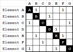
A way to make a plan for an adaptive life cycle is to make a dependency structure matrix (DSM). The dependency structure matrix consists of all design tasks in a matrix form in both rows and columns. The way the matrix works is that all tasks that depends on information from other tasks gets the box filled in. The matrix will then have a filled diagonal which simply shows that each task depends on itself. All the filled boxes below the diagonal is not a problem as they will have the required information in time since the depending tasks will be finished before the start of the relevant task. The filled boxes above the diagonal, however, depends on information from tasks that starts later. The way to handle such tasks is to either estimate the required information or simply delay the completion of the tasks [2]. The amount of such tasks can be reduced by moving the tasks around in the matrix such that the dependencies gets below or close the diagonal. The dependency structure matrix can for example be used in the design phase as an iterative tool where the architect sends a structure design to the engineer who then sends some suggested changes back to the architect and so on. A more in-depth explanation of the dependency structure matrix can be seen in Application of Dependency Structure Matrix in Time Scheduling
[edit] Implementation example of the described methods
The critical path method, critical chain method and the dependency structure matrix can all be illustrated and compared using the same example. To show the differences, a simple example is compared in the following.
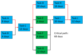
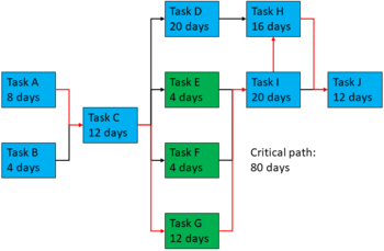
In figure 6, the critical path of the project is shown by the red path. The green tasks illustrate tasks that shares resources and it can be seen that the critical path method simply ignores this.
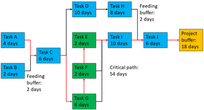
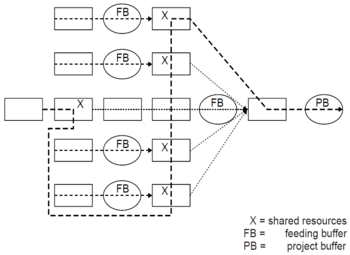
The critical chain method is illustrated in figure 7. Here it can be seen that the critical path now is resource constrained as these tasks have to be executed one by one instead of in parallel as assumed in the critical path method. The durations of the tasks are reduced since the uncertainty is moved to the project manager. This also means that a project buffer is added in the end of the critical path as well as feeding buffers are added to the non-critical paths. In this example, it can be seen that the change in method results in a shorter project time as it goes from 68 days to 54 days.
It could be a good idea to implement the last planner technique together with the critical chain. Especially when it comes to the execution of task E, F and G. In the critical chain, it has simply been decided that the order goes G, F and then E however when the project reaches this point it might be better to have another order or maybe even split up the tasks into smaller bits.
If the shared resource is assumed to be working area, it could also be a good idea to make a location based schedule of the construction site. With the use of this, the work flow could be optimized and possibly reducing the duration, since the tasks could run in parallel with perhaps a day in between. It might also be a possibility that some resources from task E and F could be reallocated to task G such that the durations would be about the same time of 3 to 4 days instead of 2, 2 and 6 days.
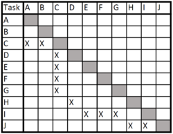
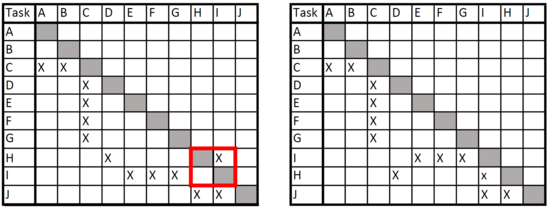
It can be seen in figure 8 that the dependency structure matrix for the current example shows no dependency problems as all the dependencies are situated below the diagonal. This also means that no further optimization of the matrix is needed. For the sake of illustrating the dependency structure matrix, a change in the dependencies is made such that task H now depends on the completion of task I.
In the left matrix in figure 9, it can be seen that there now is a dependency above the diagonal. If these tasks are in the design phase, two approaches can be made to accommodate this problem. Either the result from task I can be estimated and then feed the estimate into task H. Otherwise task I has to complete before task H can begin. In this case, it is possible to switch the places of task H and I which can solve this problem. This is illustrated in the right matrix in figure 9. This change in the order of task execution, however, also changes the critical path. This new critical path can be seen in figure 10.
[edit] Advantages and limitations
The sequential life cycle methods generally consist of strategical tools which means that they make an overall plan of a project. It is usually an advantage to make such a plan, as the total project time most likely would be longer without an idea of which tasks should be done at a given time. The sequential methods, however, are not very robust when it comes to delays. A delay in a task can result in delay of the entire project in which case the plan would have to be re-evaluated. A delay in one task can also result in further delays in other tasks that depends on the completion of the delayed task.
The adaptive life cycle methods generally consist of tactical tools which means that they go into the detailed planning throughout the project. This makes projects less vulnerable to delays as the work in each task more easily can be rescheduled as the project goes on. The adaptive methods do, however, not work without an overall plan such as the sequential methods.
Each method in both the sequential and adaptive life cycles have their own advantages as well as disadvantages. A list of the key points can be seen below.
- The critical path method
- Advantages
- It gives an estimate of the duration of the project as well as individual tasks throughout the project life.
- It is a simple method for small projects.
- Disadvantages
- It does not take resources into account.
- It is difficult to maintain the schedule in case of changes or delays in tasks.
- Uncertainty is not taken care of by the method.
- The plan has to made early in the project where the amount of information of the project is limited.
- Advantages
- The critical chain method
- Advantages
- It takes resources into account by calculating the longest resource constrained path.
- It moves the responsibility of completion time from the task managers to the project manager.
- It reduces the effect of Parkinson's law which reduces the overall project duration.
- Disadvantages
- The plan has to made early in the project where the amount of information of the project is limited.
- It does not handle the work flow in detail.
- Advantages
- Location based scheduling
- Advantages
- It enables several tasks to be executed simultaneously on the construction site without spatial conflicts.
- It reallocates resources which reduces the project time and possibly the project cost.
- Disadvantages
- The project has to be planned in detail at a relatively early stage in the project.
- It is difficult to change the plan, which makes it vulnerable to changes and delays.
- Advantages
- Last planner method
- Advantages
- Inclusion of the workers in the planning process.
- Important decisions of the detailed planning are made later in the project when more information about the project is known.
- Robust against changes and delays since the detailed planning is done continuously.
- Disadvantages
- The method can not work alone as it needs an overall plan to be based on.
- Advantages
- Dependency structure matrix
- Advantages
- Reduces the iteration time of interdependent tasks that needs information about one another. This is especially useful in the design phase.
- Disadvantages
- The method does not take the duration of the tasks into account.
- The method does not take resources needed in the tasks into account.
- Advantages
[edit] Annotated Bibliography
Winch, Graham (2010), "Managing Construction Projects. An Information Processing Approach" Second Edition, Wiley-Blackwell, United Kingdom. ISBN 978-1-4051-8457-1.
In chapter 11 of the book there are good descriptions about the critical path method, the critical chain method, critical space analysis and the last planner technique. There is also a short introduction about the dependency structure matrix.
Andersson, Niclas & Christensen, Knud (2007), "Location-based Scheduling", DTU BYG, Denmark. ISBN 9788778772411.
The report gives an in-depth description of location based scheduling based on recent literature and empirical studies.
Intelligent BIM Solutions TV, "02 SCHEDULE Location Based Management". https://www.youtube.com/watch?v=GI0MEKr5ntg
The YouTube-video gives a short introduction to how location based scheduling works with use of a simple example.
Deshmukh, Yogeeta (2013), "Project Management Life Cycles - Evolution over the years". https://www.simplilearn.com/project-management-life-cycles-evolution-article
This article gives a short explanation about the different project life cycles including the sequential and adaptive life cycles, which have been described in this article.
[edit] References
- ↑ Deshmukh, Yogeeta (2013), "Project Management Life Cycles - Evolution over the years". https://www.simplilearn.com/project-management-life-cycles-evolution-article
- ↑ 2.0 2.1 2.2 2.3 2.4 Winch, Graham (2010), "Managing Construction Projects. An Information Processing Approach" Second Edition, Wiley-Blackwell, United Kingdom. ISBN 978-1-4051-8457-1.
- ↑ 3.0 3.1 Intelligent BIM Solutions TV, "02 SCHEDULE Location Based Management". https://www.youtube.com/watch?v=GI0MEKr5ntg. Retrieved June 21, 2017.
- ↑ "Design structure matrix". Retrieved June 19, 2017, from https://en.wikipedia.org/wiki/Design_structure_matrix.
