BIM as a Management Tool in Construction Projects
RikkeWitten (Talk | contribs) (→Risk) |
RikkeWitten (Talk | contribs) (→Quality) |
||
| Line 126: | Line 126: | ||
=== Quality === | === Quality === | ||
| − | As the information in the project is automatically shared, the model is automatically updated in all linked models and the most fatal clashes of installations can be solved prior to physically starting the construction, the resulting construction/building will be of much higher quality. | + | As the information in the project is automatically shared, the model is automatically updated in all linked models and the most fatal clashes of installations can be solved prior to physically starting the construction, as mentioned in the previous subsection. Without the on site panic solutions, the resulting construction/building will be of much higher quality. |
=== Time === | === Time === | ||
Revision as of 20:40, 25 September 2016
As the Architecture, Engineering and Construction (AEC) industry evolves, the demand for more complex and unique constructions increases, and the risk for failure increases with it. Furthermore, the nature of construction projects, with their high value, long duration and multiple factors of uncertainties, often results in delays and busted budgets. The Project Manager, in the field of construction, is faced with dealing with and preferrably minimizing these risks.
In order to carry out a successful project, it is advantageous to make the project more transparent, optimize the process and the communication between the active stakeholders of the project e.g. the AEC-team. Projects based on 2D drawings are still the most common at the moment, but with the high complexity and increase of digital documentation in construction, the aspect of Information and Communication Technology (ICT) is of great importance, and within construction, Building Information Modelling (BIM) has become an effective tool for the Project Manager to reach the desired goals of a project within the given constraints.
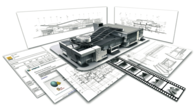
As the illustrated in Figure 1, One single model can be the digital platform where in multiple informations are stored, and thus limiting the human facot for error, as all changes are updated automatially in all views and documents. Already in 1975, this road to transparency was shortly illustrated by the "Father" og BIM, Charles M. Eastman with the following quote:
“A model can represent all three dimensions of a composition directly, while a drawing can represent only two unambiguously. Thus it takes two drawings to represent the information provided by a single model.” - Charles M. Eastman[2]
The purpose of this Wiki is to illustrate how the relatively new technology of Building Information Modelling (BIM) can be used in a Project Management regi. This will be done by listing and elaborating the benefits of BIM as a management tool/process in coretation to some of the Project Management focus areas, such as Communication, Stakeholders, Risk, Cost, Quality and Time.
Finally, the limitations of BIM will be listed and elaborated, as these are some of the areas, that needs further development or focus.
As I have worked as a Technical Designer on construction projects (based on 2D drawings in AutoCAD) since 2005, attended several BIM courses on DTU and is now working on implementing the BIM process in a small Electrical Engineering company, some parts of this article are based on experience.
Contents |
Definition of BIM
BIM (Building Information Modelling) is a digital management tool/process, containing 3D BIMs (Building Information Models). The concept of BIM is to create an intelligent platform for sharing data and construct the building virtually in 3D, before starting the physical construction. [3]
The models used in BIM are 3D parametric object based, meaning that each object contains data about how it can interact with connected objects. The object can also contain design parameters, altering the visualization of the object according to the input and the changes to an object are able to automatically change in all views. The National Building Information Model Standard Project Committee (NBIMSPC) defines BIM as following:
“A BIM is a digital representation of physical and functional characteristics of a facility. As such it serves as a shared knowledge resource for information about a facility forming a reliable basis for decisions during its lifecycle from inception onward.” [4]
The management possibilities of using BIM has developed from simple visualization into a multi functional tool, depending on the chosen dimension of modelling as illustrated in Figure 2 and listed below[5]:
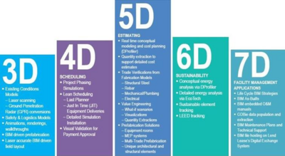
- 3D - Visualization
- The project is modelled in 3D and components contain detailed data for extraction of simple bills of quantity with limited product information, e.g. number of doors/windows in the building, but not necessary the specific product type or cost. With an accurate 3D model, it is alsp possible for manufactures to use the model for e.g. prefabrication of concrete walls, special doors/windows etc.
- 4D - Scheduling
- The 3D model is combined with a time schedule (e.g. from MS Project or similar compatible scheduling software), making it possible to simulate and manage the time aspect of the project, with the information stored in the model.
- 5D - Estimating
- The cost aspect is added to the 4D model. The bills of quantity are connected to catalouges from the suppliers, making it possible for the entrepreneur to make a much more specific bid on a tender project, as he/she knows both the quantity and manufacturer of every project. The cost estimation can, however, not be done automatically, as it is very dependent on the relationship between the tenderer/entrepreneur and the supplyer/manufacturer (the size of discounts can vary a lot within the field of construction).
- 6D - Sustainability (current development)
- An environmental aspect is added to the 5D model, making it possible to automatically generate lighting and energy consumation analysis. As the model at the current state of development already contains most of the informations needed for these analysis, and seperate semi-manual software for making these analysis already exists (e.g. Dialux for lighting and Be10 for energy consumption), the use of 6D BIM might not be too far in the future.
- 7D - Facility Management Applications (under development)
- After the construction phase has ended, and the building is finished, the detailed and information packed models can be used for facility management, as the Facility Manager then has the detailed information (such as price, supplier, material etc.) about every component in the building - all stored in one single model.
Historical development
The 2D construction drawing has been used for centuries and for complex constructions, physical models have been used to get a better understanding of the physical spaces of the construction.
BIM, as we know it today, has been 40 years in the making and already in 1975, Charles M. Eastman mentioned in an article from 1975[2] several disadvantages of both 2D drawings and the physical 3D models and described the ideal vision for a digital, multidisciplinary 3D model with the possibility of extraction of 2D drawings, lists of quantity for cost estimation and automatized clash-testing. Furthermore Eastman explained how the models should be based on components containing non-redundant data, meaning that a change in one view, would propagate to the rest of the views.
The “Building Description System (BDS)” approach, described by Charles M. Eastman[2], was further developed during the 70s and 80s and was in the USA referred to as “Building Product Models” and in Europe as “Product Information Models”. These two terms were later combined to the term "Building Information Modelling (BIM)" as we know it today and was first documented in 1992 by van Nederveen and Tolman from TU Delft in the Netherlands.[6]
Due to the limited development of the personal computer and the fact, that the construction industry has a reputation for being very slow/reluctent to adopt change[7], the further development of BIM was slowed down, and it was not until the first launch of Revit in 1999, the evolution of BIM started accellerating[8]. 3D modelling software such as ArchiCAD, was already on the market, but Revit revolutionized the industry, with a new type of userface. Where ArchiCAD-models were created by coding, the Revit-models were created by modelling each component in a more WYSIWYG kind of userface. The use of the program was more intuitive, than it's predeccessors, which meant that more people were keen on learning how to use it.
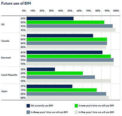
The use of BIM has expanded during the last decade and in 2016, and as illustrated on Figure 3 from the NBS [9], 81% of the respondents in Denmark were using BIM. Furthermore, the report from NBS showed how Canada is in front, with Denmark, as 71% the respondents were using BIM, whereas Japan and the UK had responses of only 49% and 50% respectively and the Czech Repuplic was far behind with only 30% of the respondents using BIM.
However, in spite of the scattered results of present use of BIM in the five participating countries, all of them seems to believe, that BIM is the future, as 85-95% of all five countries believe, that they will be using BIM within five years.
Application
Building Information Modelling (BIM) can be applied to any size of construction project as a tool or process of managing the fundamental areas in Project Management. Some of the most common application areas, listed by Marketing Analytic, Rachel Burger [10], are as following:
- 3D visualization of buildings:
- A 3D models have been used for visualization of project for a long time, which is why many users and developers often stop at this application of BIM.[10] However, the Building Information Models are so much more than a vizualisation tool, as illustrated in the following points of application.
- Change management (clash tests, revisions):
- By using a shared server (e.g. Revit Sever) a central model can be created, for all the discipline models to be linked into. By linking the models together, changes in one model, are automatically changed in all views (in contrary to the 2D way of working, where e.g. new architectural drawings would have to be manually imported to all electrical-, ventillation-, water- and plumbing drawings as xreferences, leaving many steps for failure).
- The 3D models from the architects and all the engineering disciplines can be tested for clashes between the models.
- Construction simulation (4D):
- The time estimation can be visualized with adding the time-aspect to the 3D model by combining it with a time schedule of the project. In the simulation software (see "Tools" for further information), each object in the 3D model is connected to a task in the schedule, in order to simulate the construction from start to finish. An example of the result of a simulated construction, is illustrated in the video from Autodesk on the right.
- Data management (5D):
- The BIMs of today, can contain large amount of information, that are automatically shared along with the model itself.
- Bills of quantities can be automatically created from the information, stored in each object in the model (e.g. windows, doors, lighting fixtures etc.). In addition to the built-in bills of quantity in e.g. Revit, each object can be provided with a unique code (in Denmark CCS (Cuneco Classification System) is used), making it possible to make unique references from the model to the discriptions from each engineering dicipline. This direct and unique code is based on a standard system (CCS) and further described in the ICT contract (Information and Communication Technology contract) of the specific project, wherefore everyone working in the model, are using the same type of coding-system and all codes in the model are garantied to be unique. The coding can be done manually, but additional software can be used to generate these codes, based on object type, -placement etc. (see section "Tools" for list of software or "Annotated Bibliography" for additional information)
- Operational management (6D + 7D):
- The model can be used for estimating energy consumption for the entire lifecycle of the building, and can be used after erection by the Facility Manager for maintanence and for further remodelling or extension of the building.
Use and Benefits
The measured percentage benefits from using BIM in construction projects are based on data from 32 major projects, gathered by Stanford University’s Center for Integrated Facilities Engineering (SUCIFE).[15] The benefits of BIM as an ICT-tool in construction are closely related to the actual use of the model. BIM has the possibility to be an effective tool for managing multiple challenges in construction projects.
An example of some of the benefits of using BIM, is the clash detection tool. As mentioned earlier in the article, construction projects are planned and designed by multiple departments, companies and fields of expertease and therefore communication is the key to successfully manage such a project. From my work as a Technical Designer (/Technical Drawer), I have expeirienced a lot of these benefits in my current project of implementing 3D and BIM in a small Electrical Engineering counseling company, wherefore not all information has references.
Communication
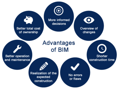
As construction projects are highly dependent on coordination of multiple fields of construction and therefore multiple people from different organizations. [16] By using BIM the project can be made more "transparent", as everyone in the AEC-team can view the project at the same time, and all changes are updated emiediately for everyone to see, as illustrated as one of the main advantages in Figure 4.
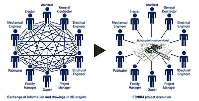
The transparency of the projects also concerns the workflow, as the former 2D process required e.g. the architect to draw, print and send the numourous drawings (today we print and send mostly pdf, but not more than 10 years ago, we printed and send physical drawings) to the different engineers (geotechnical, construction, ventilation, water/plumbing, electrical) for them to use for planning their design and use as a base for their drawings. The process of sending drawings back and forth (even by e-mail of pdf-drawings), the architects could have changed their design by the time, the engineers had done their design, which results in a lot of revisions to keep track on. From my expirience, the people who has to supply another field with information and drawings, don't always know what information is needed, and a lot of time is spent, calling, explaining and requesting the right information. The complex workflow is illustrated on the left side of Figure 5.
In large, multistorage constructions, different tasks can be carried out by different constractors (carpentry, painting, electrical etc.) simultaniously, which can cause conflicts and unecessary waiting, if too many different things are supposed to be done in the same space at the same time. The simulated construction is not only used as a full video of the whole duration of the build, but images for each week can be extracted with the work of current week highlighted. These images can be brought to contractors meetings in order for planning the upcoming week and avoid having all the workers working in the same location at the same time.
Stakeholder
The stakeholders of a construction project span from the professionals in the decision making and design phase, such as engineers, users, neighbours, investors etc. The 3D visualization part of BIM can be used to manage stakeholders expectations as it gives a more relatable visual of the product, in comparison to the 2D drawings.
Risk
In every project, the Project Manager is faced with uncertainties and risks, wherefore it is important to be able to act and react to unexpected events, exploit possibilities and plan for the unknown. In construction, the most common uncertainties and risks are time and economy overrun due to failure in communication, changes in the work/design, complications on site etc. [17] By using BIM as a management tool, some of these risks can be reduced by planning for the unknown and simulating multiple outcomes.
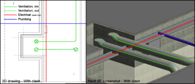
One of the common risks when creating a construction project, is the "clashes/collitions" of installations. As most installations are run above suspended ceilings, where there is wery little space, clashes of e.g. ventilation ducts and electrical wiring in cable trays are almost enevitable. Before BIM, the ventilation engineer and the electrical engineer might be situated in different companies and had their seperate 2D drawings, containing only their own duct or cable tray. As the equipment was often only illustrated by a single line (instead of the actual width of the duct/tray), it was very likely, that they ended up being drawn in the same spot or intersecting at some point, as illustrated on Figure 6, shich is an example from my work, where an electrical tray runs through both ventilation ducts and a plumbing pipe. Collitions like this would have to be solved by the electrician on site (as the cable tray is the smallest and most easy to move/manipulate), which could be very time consuming and would require more materials than first estimated. In worst case, there would not be room for the cable tray elsewere above the ceiling, which might require the engineers to come up with a different, less desired solution.
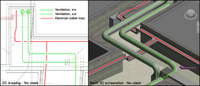
With BIM, all the installations are modelled in 3D, making it possible for the electrical engineer (or his/her Technical Designer) to see the precise placement and size of the other installations and solve the collision digitally by moving the cable tray. Regularly conducted clash/collision tests during the design phase would furthermore catch any undetected clashes, which then also can be solved digitally before the construction phase is initiated, thus saving both time and money. An example of a solved clash between a cable tray and ventilation ducts are illustrated on Figure 7, where the cable tray passes under the ducts, instead of going through them.
Cost
Since the models in BIM contain information about all the components in the building, detailed lists of quantity can be extracted and the study from SUCIFE found that the cost estimation accuracy was within 3% as compared to traditional estimates[15], where the a cost estimation was made separately for each discipline and multiplied with a safety factor, causing the final estimate to be unnecessarily far on the safe side.
During the construction phase, research has shown how up to 40% of unbudgeted changes had been eliminated by using BIM in the design phase and how through clash detections would result in savings of up to 10% of the contract value.[15]
Quality
As the information in the project is automatically shared, the model is automatically updated in all linked models and the most fatal clashes of installations can be solved prior to physically starting the construction, as mentioned in the previous subsection. Without the on site panic solutions, the resulting construction/building will be of much higher quality.
Time
With the use of a 4D Building Information Model, the time can be managed through simulated construction. A simulation can reveal time conflicts early in the design phase, which can then be solved before they become a delay. By preventing delays and being able to pre-plan for conflicts, the research from SUCIFE showed up to 7% reduction in project duration in the 32 projects.[15]
Also the duration of the design phase has potential to be reduced, as the research has found that the use of BIM resulted in up to 80% reduction in time taken to generate a cost estimate.[15] This reduction is caused by the detailed bills of quantity, that can be directly extracted from the model, which used to be counted manually from the 2D drawings.
Tools
When using BIM, it is important to use the right software for the extended desire of use, and to ensure, that the different chosen software are compatible.
The following list some of the more popular software for each use of BIM:
- 3D Model
- Modelling:
- - Autodesk Revit [1] (Paid license)
- - Magicad [2] for MEP modelling (compatible with Revit, paid license)
- - Archicad[3] (Free demo version, Paid License for full version)
- Clash Testing:
- - Autodesk Navisworks [4] (compatible with Revit, paid license)
- - Solibri [5] (Uses IFC files, can be exported from most modelling software. Paid license)
- Classification Coding:
- - Spine [6] (compatible with Revit, paid license)
- 4D model (3D + time)
- Simulation of construction:
- - Navisworks [7]
- Time scheduleing:
- - MS Project [8] (compatible with Navisworks)
- 6D model (5D + envireonmental)
- Energy consumption calculation:
- - AGACAD [9] (compatible with Revit, paid license)
- Lighting calculation
- -DiaLUX [10] (compatible with architectural software, freeware)
Limitations
As mentioned previously, BIM can be applied advantageously in any size of construction project, however, at the current state of BIM adoption, the economical cost/benefit is more obvious in the larger, more complex construction projects.
- Education/Modelling skills
- Cost of software
- Added cost and time in design phase (making the model)
- Education/Modelling skills
- As BIM requires 3D modelling done for all engineering fields (e.g. water, plumbing, ventilation, construction and electrical) in order to gain the most value in terms of clash-testing, the modelling skills of the individual person and the cost of the 3D modelling software, can be limiting for smaller projects and companies. It is possible for companies to purchase project specific modelling assistance, however, the decision to spend the extra money, highly depends on the size and complexity of the project in question.
- Cost of software
- The commercial 3D software solutions, such as Revit and ArchiCAD, are very expensive, causing the smaller companies to delay the adoption of BIM. In addition to the 3D modelling software, the aspects of CCS coding and cost estimation, requires add-ins, which also are relatively expensinve.
- Added time in design phase
- A detailed model can be more timeconsuming to create, than a project based on 2D drawings, however the time gained with the optimized communication and the fact that e.g. sections of the building can be created automatically instead of having to be drawn from scratch, which is the case in 2D, might outweigh the extra time spent. And it can ofcourse be argued that a skilled and expeiriensed modeller, can create the model even faster than a drawer can produce the same amount of drawings in 2D.
As the economical benefits of BIM are not as upfront and visible as the added expense of using BIM are, Project managers are still reluctant to spend the extra cost in the beginning of a project, eventhough studies has shown how the use of BIM is advantegous for the outcome of construction projects.
Annotated Bibliography
For further reading about BIM,
Books
Graham M. Winch - Managing Construction Projects, An Information Processing Approach, 2nd Edition 2010, Wiley-Blackwell
Summary: This
Articles
Charles M. Eastman, "The Use of Computers Instead of Drawings In Building Design" (Direct link to pdf-file: [11])
Websites
Additional Standards and Guidelines
CCS Coding (Cuneco Classification System) - CCS Identifikation - Regler, definitioner og eksempler (Direct link to pdf-file: [12]) (NB! Only in Danish)
Summary: This
bips - A104 Dokumenthåndtering[13] (NB! Requires subscription to bips.dk, only in Danish)
Summary: This
References
- ↑ http://www.graphisoft.com/archicad/open_bim/about_bim/
- ↑ 2.0 2.1 2.2 Charles M. Eastman, The Use of Computers Instead of Drawings In Building Design, AIA Journal, March 1975
- ↑ Deke Smith, An Introduction to Building Information Modeling (BIM), Journal of Building Information Modeling, Fall 2007
- ↑ Saeed Rokooei, Building Information Modeling in Project Management: Necessities, Challenges and Outcomes, 2005
- ↑ 5.0 5.1 http://www.bimpanzee.com/about-building-information-modeling--bim-.html
- ↑ 6.0 6.1 http://www.bauen-digital.ch/assets/Medienmitteilung/1603-NBS-International-BIM-Report.pdf
- ↑ http://www.bimpanzee.com/about-building-information-modeling--bim-.html/
- ↑ https://forums.autodesk.com/t5/revit-architecture-forum/first-version-of-revit/td-p/1544647
- ↑ http://www.bauen-digital.ch/assets/Medienmitteilung/1603-NBS-International-BIM-Report.pdf%7C/
- ↑ 10.0 10.1 http://blog.capterra.com/the-top-6-free-bim-software-tools/
- ↑ https://www.youtube.com/watch?v=tQkDRXo7tLM
- ↑ https://www.google.dk/url?sa=t&rct=j&q=&esrc=s&source=web&cd=1&cad=rja&uact=8&ved=0ahUKEwjox_qBgKXPAhVSKywKHTPeBxoQFggcMAA&url=http%3A%2F%2Fmth.dk%2F~%2Fmedia%2FCampaign%2FManKanGodt%2FCase%2520Virtuelt%2520byggeri%2FDocuments%2FEn-staerkere-byggeproces-BIM-i-teori-og-praksis.ashx&usg=AFQjCNEBrkmJVxDdl855kXt_o_LrCFZykA&sig2=mVkD7sRsiJWwB9Vq6WIDuQ
- ↑ Illustration by RikkeWitten
- ↑ 14.0 14.1 Illustration by RikkeWitten
- ↑ 15.0 15.1 15.2 15.3 15.4 http://ascelibrary.org/doi/10.1061/%28ASCE%29LM.1943-5630.0000127
- ↑ Joana Geraldi, Christian Thuesen and Josef Oehmen, How To DO Projects, Version 0.5, 27. July 2016
- ↑ http://www.designingbuildings.co.uk/wiki/Risk_in_building_design_and_construction