Metra Potential Method
| Line 37: | Line 37: | ||
===Graphic representation=== | ===Graphic representation=== | ||
| − | '''Task:''' A task is represented by a frame and is identified by its name. The earliest start and latest start corresponding to the task are listed in the top of the frame. The graphic representation of a task is illustrated in the '''Figure 1''', on the right. [[File:Case2.PNG|thumb|280px|'''Figure 2''', Succession constraint representation]] | + | '''Task:''' A task is represented by a frame and is identified by its name. The earliest start and latest start corresponding to the task are listed in the top of the frame. <ref name="MPM3" /> The graphic representation of a task is illustrated in the '''Figure 1''', on the right. [[File:Case2.PNG|thumb|280px|'''Figure 2''', Succession constraint representation]] |
| − | '''Succession constraint:''' Succession constraints are represented by an arrow which goes from the antecedent task to the next one. The constraint duration corresponds to the starting task duration. This values is written above the arrow. | + | '''Succession constraint:''' Succession constraints are represented by an arrow which goes from the antecedent task to the next one. The constraint duration corresponds to the starting task duration. This values is written above the arrow. <ref name="MPM3" /> |
The graphic representation of a succession constraint is illustrated in the '''Figure 2''', on the right. | The graphic representation of a succession constraint is illustrated in the '''Figure 2''', on the right. | ||
| Line 47: | Line 47: | ||
===Convention rules=== | ===Convention rules=== | ||
| − | Four main rules apply when organizing the tasks network in the frame of MPM method: | + | Four main rules apply when organizing the tasks network in the frame of MPM method <ref name="MPM3" /> : |
* Any stage has an origin stage as beginning, and an end stage as end. | * Any stage has an origin stage as beginning, and an end stage as end. | ||
| Line 119: | Line 119: | ||
|} | |} | ||
| − | A first approach is made by integrating as much as previous tasks as possible. An efficient way to list these previous tasks consists in making a table as illustrated on the '''Table 1''', on the right. Indeed, as first step to determine the order of succession of tasks consists in writing for each task the list of previous tasks which need to be achieved before its execution. | + | A first approach is made by integrating as much as previous tasks as possible. An efficient way to list these previous tasks consists in making a table as illustrated on the '''Table 1''', on the right. Indeed, as first step to determine the order of succession of tasks consists in writing for each task the list of previous tasks which need to be achieved before its execution. <ref name="MPM3" /> |
| Line 231: | Line 231: | ||
====Assigning the tasks duration in the MPM grid==== | ====Assigning the tasks duration in the MPM grid==== | ||
| − | Each stage is characterized by an earliest start and a earliest finish. These specific dates are defined according to of the duration of tasks. The method to calculate the duration of tasks is not specified in this article. Briefly, this duration depends on the workload needed and the number of resources available to achieve the task. | + | Each stage is characterized by an earliest start and a earliest finish. These specific dates are defined according to of the duration of tasks. The method to calculate the duration of tasks is not specified in this article. Briefly, this duration depends on the workload needed and the number of resources available to achieve the task. <ref name="MPM3" /> |
In the example developed as an illustration for the MPM implementation, it is considered that the task duration were already set, as illustrated in the table on the left ('''Table 4'''). | In the example developed as an illustration for the MPM implementation, it is considered that the task duration were already set, as illustrated in the table on the left ('''Table 4'''). | ||
| Line 247: | Line 247: | ||
====Adding the Earliest Start to the MPM grid==== | ====Adding the Earliest Start to the MPM grid==== | ||
| − | The initial stage of the project starts on day 0. From this point, task duration of the task upstream is added to its earliest start in order to obtain the earliest start of task downstream. The calculation of each earliest start may be performed using a table, as illustrated below ('''Table 5''') for the example. | + | The initial stage of the project starts on day 0. From this point, task duration of the task upstream is added to its earliest start in order to obtain the earliest start of task downstream. <ref name="MPM3" /> The calculation of each earliest start may be performed using a table, as illustrated below ('''Table 5''') for the example. |
{| class="wikitable" style="margin: auto;" | {| class="wikitable" style="margin: auto;" | ||
| Line 308: | Line 308: | ||
====Adding the Latest Start to the MPM grid==== | ====Adding the Latest Start to the MPM grid==== | ||
| − | For the last task (Z in the example), the earliest start is the same as the latest start. Then, from this last task of the project, the duration of the antecedent tasks are subtracted step by step to set the latest start of the downstream task. The latest start of a task corresponds to the difference between the latest start of the task directly upstream and its duration. | + | For the last task (Z in the example), the earliest start is the same as the latest start. Then, from this last task of the project, the duration of the antecedent tasks are subtracted step by step to set the latest start of the downstream task. The latest start of a task corresponds to the difference between the latest start of the task directly upstream and its duration. <ref name="MPM3" /> |
As for the earlier start, it could be useful to create a table in order to calculate the latest starts of each task, as illustrated in the table below ('''Table 6''') for the example. | As for the earlier start, it could be useful to create a table in order to calculate the latest starts of each task, as illustrated in the table below ('''Table 6''') for the example. | ||
Revision as of 14:39, 24 September 2015
The Metra Potential Method, or MPM, is a project management tool, invented in 1958 by French researcher Bernard Roy. [1], [2], [3] MPM is used to describe, organize and plan the several tasks constituting a project development. This management method is similar to the PERT method. It consists of an oriented graph, whose summits represent tasks and the connections represent anteriority constraints. Thanks to the use of the MPM method, a critical path is identified easily by simply reading the chart, and the length of the critical path is represented directly .
Contents |
History
Bernard Roy is a French researcher born in 1934, widely recognized as a pioneer in the field of operational research in France. His works form one of the foundations of scientific approaches to decision support. In 1958, he invented the Metra Potential Method (MPM, for Méthode des Potentiels Metra in French), a method based on the Graph Theory. [1]
This method was first created as a tool provided for a crank shafts factory called Mavilor. Very soon after its creation, MPM was used for the construction of the superstructures of cruise liner France. In the beginning of the 1960’s, this method was involved in the development of the airplane program Concorde, as well as in the construction of the first generation of nuclear plants in France.
Concept overview
Created the same year as the PERT method, the MPM method is a system of representation and optimization of project tasks. This method can be considered to be half-way between Gantt Graph and PERT representation. It allows the user to prioritize a large number of tasks, taking into account the anteriority constraints linking these several tasks.
The main goal leading to the creation of this new management method was to reduce the complexity of the Gantt chart, taking into account the dependency relationships between multiple tasks (precedence, inheritance, etc.) and also the evolution of these constraints along the time.
Similarly to the PERT method, the main benefit of MPM is to reduce the time required to achieve a project, but this method only takes into account aspects such as scheduling, deadlines or delays. It cannot be used in the field of budget or resources management. By precisely describing the dependency between each task, MPM optimizes speediness of the process providing a graphical representation under the form of a network. Thus, all information related to a same operation are grouped under a single node, which facilitates the identification of the critical path.
Allowing an easy identification of the critical path, the MPM is used to determine the minimum time required to conduct a project. Moreover, this method affords to define the dates on which the various tasks involved in the project may or must begin to ensure that this minimum time is respected.
Implementation of the method
Terminology
Task: In the frame of project management, a task is the basic division of the work required to produce the result. The task evolves from an initial state to a final state. Each task has a duration and cost.
Previous task: A task which, with respect to another, has to be performed before.
Antecedent task: A task which is immediately prior to another task.
Stage: A step is the beginning or the end of a task. It has no time nor cost.
MPM grid: This is all of the tasks and stages that define the project. It highlights the relationships between tasks and stages.
Critical path: The longest possible continuous path from the initial task starting to the terminal task ending; it determines the total amount of time required for the project delivery. Any time delays along this path will delay the execution of the project by at least the same amount.
Float (or slack): A float is a measure of the available extra time and resources needed to complete a task. It indicates the possible delay that an individual task may have without delaying the all process.Earliest start: It corresponds to the earliest date when the task may start.
Latest start: It corresponds to the latest date when the task may start.
Graphic representation
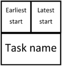
Task: A task is represented by a frame and is identified by its name. The earliest start and latest start corresponding to the task are listed in the top of the frame. [3] The graphic representation of a task is illustrated in the Figure 1, on the right.
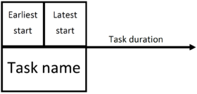
Succession constraint: Succession constraints are represented by an arrow which goes from the antecedent task to the next one. The constraint duration corresponds to the starting task duration. This values is written above the arrow. [3]
The graphic representation of a succession constraint is illustrated in the Figure 2, on the right.
Convention rules
Four main rules apply when organizing the tasks network in the frame of MPM method [3] :
- Any stage has an origin stage as beginning, and an end stage as end.
- A stage can be achieved only when all the tasks that precede it are finished.
- No task can be performed if the original stage has not been reached.
- By convention, a MPM network must be terminated with a single task (called Z generally) that determines the end of the project. This task will have no duration.
| Task | Previous tasks |
|---|---|
| A | - |
| B | A |
| C | A |
| D | - |
| E | AB |
| F | ACD |
| Z | ABCDEF |
Implementation of the methodology
List of tasks
Achieving a graph showing the analysis of a scheduling problem requires a preliminary study of the various tasks to be considered, their duration, and the relationships between tasks (mainly constraints of anteriority and antecedence). A special attention should be paid when it comes to achieve this preliminary study.
| Task | Antecedent tasks |
|---|---|
| A | - |
| B | A |
| C | A |
| D | - |
| E | B |
| F | CD |
| Z | EF |
A first approach is made by integrating as much as previous tasks as possible. An efficient way to list these previous tasks consists in making a table as illustrated on the Table 1, on the right. Indeed, as first step to determine the order of succession of tasks consists in writing for each task the list of previous tasks which need to be achieved before its execution. [3]
Then, in order to ease the work, only the antecedent tasks will be kept. In the example case, task A is not directly prior to tasks E or F. As task A cannot be represented more than once in the MPM grid, it is useless to keep it on the table. This way, it is possible to obtain the Table 2, on the left.
Determination of tasks levels
In order to clearly establish the MPM grid, it is appropriate to define an achievement level for each task. Such a level is a moment in time. The higher the level is, the faster the task is from the first stage of the project.
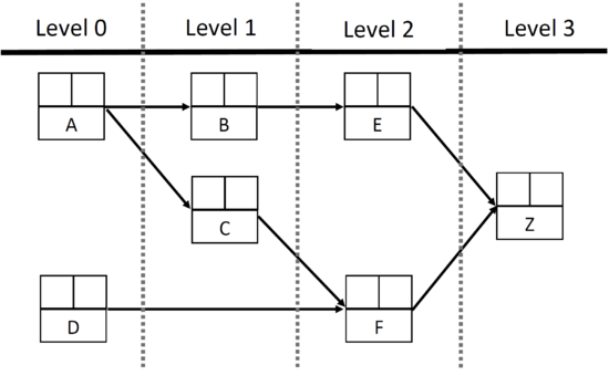
The aim consists in identify the level of each tasks to obtain the global aspect of the MPM grid. To do so, a table may be created to identify which tasks don't have antecedent task for each level. The table below (Table 3) illustrates the method in the example case.
| Task | Antecedent tasks | Level 0 | Level 1 | Level 2 | Level 3 |
|---|---|---|---|---|---|
| A | - | - | - | - | - |
| B | A | |
- | - | - |
| C | A | |
- | - | - |
| D | - | - | - | - | - |
| E | B | B | |
- | - |
| F | CD | C |
|
- | - |
| Z | EF | EF | EF | |
- |
| Tasks constituting the level | AD | BC | EF | Z | |
Create this table allows to plot the global layout of the MPM grid, as illustrated below (Figure 3) in the case of the example.
At this step of the methodology process, there are no numbers in the MPM grid, only the global layout of the graph. This gives an overview about the succession order of the tasks.
| Task | Task duration |
|---|---|
| A | 3 |
| B | 7 |
| C | 6 |
| D | 11 |
| E | 8 |
| F | 5 |
| Z | 0 (End task, no duration) |
Assigning the tasks duration in the MPM grid
Each stage is characterized by an earliest start and a earliest finish. These specific dates are defined according to of the duration of tasks. The method to calculate the duration of tasks is not specified in this article. Briefly, this duration depends on the workload needed and the number of resources available to achieve the task. [3]
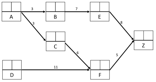
In the example developed as an illustration for the MPM implementation, it is considered that the task duration were already set, as illustrated in the table on the left (Table 4).
These information allows to fill partially the MPM grid, as illustrated below (Figure 4).
Adding the Earliest Start to the MPM grid
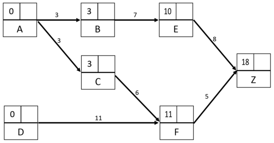
The initial stage of the project starts on day 0. From this point, task duration of the task upstream is added to its earliest start in order to obtain the earliest start of task downstream. [3] The calculation of each earliest start may be performed using a table, as illustrated below (Table 5) for the example.
| Task | Task duration | Antecedent tasks | Calculation of earliest start | Earliest Start |
|---|---|---|---|---|
| A | 3 | - | 0 (level 0) | 0 |
| B | 7 | A | 0+3=3 | 3 |
| C | 6 | A | 0+3=3 | 3 |
| D | 11 | - | 0 (level 0) | 0 |
| E | 8 | B | 3+7=10 | 10 |
| F | 5 | CD | |
11 |
| Z | 0 | EF | 10+8=18 or |
18 |
When a task is conditioned by more than one single antecedent task, the higher sum is kept as earliest start. Thus, in the example, F is conditioned by the execution of both tasks C and D, the earliest start for task F is set to be 11 days, corresponding to the minimum time needed to achieve D, higher than the minimum time to achieve C.
These information allows to fill the cells dedicated to the Earliest Starts in the MPM grid, as illustrated below (Figure 5).
Adding the Latest Start to the MPM grid
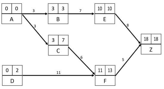
For the last task (Z in the example), the earliest start is the same as the latest start. Then, from this last task of the project, the duration of the antecedent tasks are subtracted step by step to set the latest start of the downstream task. The latest start of a task corresponds to the difference between the latest start of the task directly upstream and its duration. [3]
As for the earlier start, it could be useful to create a table in order to calculate the latest starts of each task, as illustrated in the table below (Table 6) for the example.
| Task | Task duration | Posterior tasks | Calculation of latest start | Latest Start |
|---|---|---|---|---|
| A | 3 | BC | |
0 |
| B | 7 | E | 10-7=3 | 3 |
| C | 6 | F | 13-6=7 | 7 |
| D | 11 | F | 13-11=2 | 2 |
| E | 8 | Z | 18-8=10 | 10 |
| F | 5 | Z | 18-5=13 | 13 |
| Z | 0 | - | 18 (End Task) | 18 |
When a task is directly followed by more than one single posterior task, the lower subtraction is kept as latest start. Thus, in the example, A has B and C as posterior tasks, so the latest start for task A is set to be 0 and not 4. In this case, if the latest start for task A was 4, it would engender a potential 4 days delay for tasks B and E, leading to a 4 days delay for the all project.
These information allows to fill the cells dedicated to the Latest Starts in the MPM grid, as illustrated below (Figure 6).
Now, the MPM grid is completed.
MPM grid analysis
Once the MPM grid is completed, it is possible to deduce the following characteristics: critical paths, free float and total float.
Critical path
When observing a MPM grid from the starting task to the end task (Z), it appears that it is generally possible to take various paths to connect the beginning to the end. Each paths is represented by a succession of tasks (rectangles) and succession constraints (arrows). The successive realization of the various tasks constituting a path has a total duration, depending on the duration of each of these tasks. This total duration is called: path length.
The minimum time to achieve a project corresponds to the length of the longest path. Indeed, the minimum duration of the project execution cannot be less than the sum of duration required to achieve the worst succession of asks in terms of time. This longest path is called critical path.
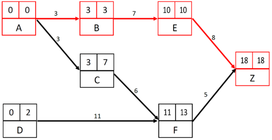
Graphically, the critical path is the suite of tasks of the MPM which have a zero float (earliest start=latest start). The tasks of this path are called critical tasks. The sum of all the critical tasks duration indicates the minimum length of the project. Any delay in one of these tasks causes an equal delay to the end date of the project. Sometimes, there may be several critical paths, which have obviously the same length. In the figure below (Figure 7), the critical path is highlighted with the red cells and red arrows.
Floats
For the task which don’t have a zero float (earliest start<latest start), two floats may be defined.
The free float is the maximum delay allowed to start a task without having an impact on the earliest starts of the following tasks.
The total float is the maximum delay allowed to start a task without having an impact on the latest starts of the following tasks.
The task with a free and total float (tasks non critical) are interesting from the project management perspective because they can be used to smooth the resources and the costs of the project throughout its development.
On the other hand, as said previously, on the critical path all floats worth zero. It results that the bigger the number of critical tasks is with respect to the total number of tasks, the lower is the elasticity of the project.
Advantages
By comparison to the PERT method, the MPM method has the advantage that its graphic representation doesn’t need to have recourse to fictive tasks, as it is sometimes needed for the implementation of the PERT method.
Although the PERT method was the first one imposed in project management, it appears that, from the 1980’s, the MPM method tends to supplant it. Indeed, this method is much more flexible and more easily adaptable to the automation of data processing, particularly when it deals with calculation algorithms and graphic representation.
Limitations
In contrast to the GANTT chart, the MPM method doesn’t provide directly a way to identify and manage the costs of tasks and the resources needed to achieve them.
