Critical Path Method (CPM)
(→References) |
(→References) |
||
| Line 297: | Line 297: | ||
== References == | == References == | ||
| − | 1. | + | 1. [http://eu.wiley.com/WileyCDA/WileyTitle/productCd-0471620572.html] |
Revision as of 21:05, 2 October 2017
Critical Path Method or CPM, is a tool used in the planning and management of different types of projects such as construction, software development, research programs, product development, sales promotion and etc. It is essentially a mathematically based algorithm of network diagrams that depicts the sequence and interrelation of all the component parts of a project and is well suited for the construction industry. In comparison to the conventional methods of planning and scheduling of construction works - bar charts and progress diagrams - Critical Path Method proves to be more useful and precise as it allows the quick evaluation and comparison of alternative work programs, construction methods, types of equipment and etc.
The time-cost problem in the construction sector is forever debatable and has an infinite number of solutions. Today, the Critical Path Methods provides a systematic procedure of correlating cost and time of each activity involved in the construction project, to provide an optimum solution. It is a crucial tool used in construction management as it provides varying degree of involvement by the management to suit the needs and objectives of the project.
Contents |
Historical Background
The critical path technique had its origin from 1956 to 1958 in two parallel but different problems of planning and control in projects in the United States.
In the first case, the US Navy was concerned with the control of contracts for its Polaris Missile program. As the contracts comprised of research, development and manufacture work of newly developed parts, the probability of completion dates for each contract was determined. This procedure was referred to as Program Evaluation and Review Technique, abbreviated to PERT. PERT did not originally include cost estimates, but subsequent inclusion of cost data in the system is called PERTCO, that is PERT with costs. It is therefore important to understand that PERT systems involve a probability approach and are better suited for projects where big uncertainties exist.
In the second case, the EI du Pont de Nemours Company was constructing huge chemical plants in America. These projects required that both time and cost be estimated accurately. This method of planning and control that was developed was initially called Project Planning and Scheduling (PPS), which covered the design, construction and maintenance of large and complex projects using realistic estimates of time and cost. This method has since been developed into Critical Path Method, (CPM).
Critical Path Method Terminology
Planning
Planning, is the process of choosing a single method and order of work to be adopted for a project from all the various ways and sequences in which the optimum result can be achieved. This is schematically shown as the CPM network diagram.
Scheduling
Scheduling is the determination of the timing of the operations comprising the project and their assembly for the overall completion time. This can only be done after the project plan has been defined and modelled as a network diagram.
Network Diagram, Activity and Event
A network is a flow diagram constituting of activities and events that are connected logically and sequentially.
Well defined jobs or tasks are called activities. These are represented by arrows in a network diagram.
The beginning or end of each activity constitutes an event of the project.In a network diagram, events are represented by nodes. These can be circular, square, rectangular or oval in shape.
Dummy
A dummy is a type of operation in the network which neither requires any time nor any resources, but is merely a device to identify a dependence among operations. A dummy is represented by a dashed arrow.
Advantages of Critical Path Method
Listed below are the advantages of using the Critical Path Method in planning and scheduling in the management of a project:
1. It shows the graphical view of the project.
2. It discovers and makes dependencies visible.
3. It helps in project planning, scheduling, and controlling.
4. It helps in contingency planning.
5. It shows the critical path, and identifies critical activities requiring special attention.
6. It helps you assign the float to activities and flexibility to float activities.
7. It shows you where you need to take action to bring project back on track.
Disadvantages of Critical Path Method
The following are the disadvantages of the Critical Path Method:
1. It does not allow to track the people and the resources utilised in an activity.
2. The network diagram could become extremely complicated for a large scale project.
Characteristics of Critical Path Method Projects
The following are the primary characteristics of any network diagram used in a CPM project:
1. The project to be planned should consist of clearly recognisable activities.
2. These activities must have definite commencement and completion dates.
3. The events must occur in a definite pattern and must have a technological sequence.
Steps Followed in Critical Path Method
The process of using critical path method in project planning phase has the following six steps.
Step 1: Activity Specification
Use of the Work Breakdown Structure (WBS) to identify the activities involved in the project. This is the main input for the critical path method.
In activity specification, only the higher-level activities are selected for critical path method.
When detailed activities are used, the critical path method may become too complex to manage and maintain.
Step 2: Activity Sequence Establishment
In this step, the correct activity sequence is established. For which there are three questions for each task on the list.
1. Which tasks should take place before the current task is executed.
2. Which tasks should be completed at the same time as the currenttask.
3. Which tasks should be executed immediately after the current task.
Step 3: Network Diagram
Once the activity sequence is correctly identified, the network diagram can be drawn.
Although the early diagrams were drawn on paper, there are a number of computer software, such as Primavera, for this purpose nowadays.
Step 4: Estimates for Each Activity
This could be a direct input from the WBS based estimation sheet. Most of the companies use 3-point estimation method or COCOMO based (function points based) estimation methods for tasks estimation.
Such estimation information can be used for this step of the process.
Step 5: Identification of the Critical Path
For this, following four parameters of each activity of the network are identified:
1. Earliest start time (ES) = The earliest time an activity can start once the previous dependent activities are over.
2. Earliest finish time (EF) = ES + activity duration.
3. Latest finish time (LF) = The latest time an activity can finish without delaying the project.
4. Latest start time (LS) = LF - activity duration.
The float time for an activity is the time between the earliest (ES) and the latest (LS) start time or between the earliest (EF) and latest (LF) finish times.
During the float time, an activity can be delayed without delaying the project finish date.
The critical path is the longest path of the network diagram. The activities in the critical path have an effect on the deadline of the project. If an activity of this path is delayed, the project will be delayed.
In case if the management needs to accelerate the project, the time required for critical path activities should be reduced.
Step 6: Critical Path Diagram to Show Project Progresses
Critical path diagram is a live artefact. Therefore, this diagram should be updated with actual values once the task is completed.
This gives more realistic figure for the deadline and the project management can know whether they are on track regarding the deliverable.
Example of Critical Path Method
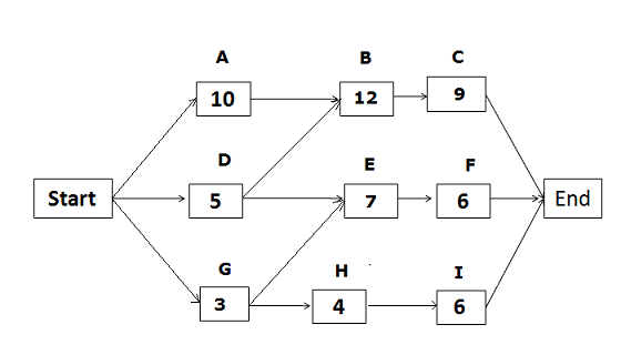
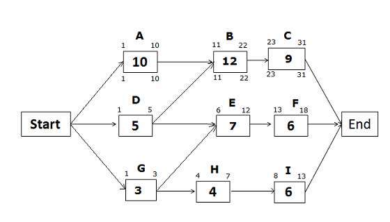
Based on the below network diagram, identify the total paths, critical path, and float for each path.
The above network diagram has five paths. The paths and their duration are as follows:
1. Start -> A -> B -> C -> End, Duration: 31 days. 2. Start -> D -> E -> F -> End, Duration: 18 days. 3. Start -> D -> B -> d -> End, Duration: 26 days. 4. Start -> G -> H -> I -> End, Duration: 13 days. 5. Start -> G -> E -> F -> End, Duration: 16 days.
Since the duration of the first path is the longest, it is the critical path. The float on the critical path is zero.
The float for the second path “Start -> D -> E -> F -> End” = Duration of the critical path – Duration of the path “Start -> D -> E -> F -> End” = 31 – 18 = 13
Hence, the float for the second path is 13 days.
Using the same process, we can calculate the float for other paths as well.
Float for the third path = 31 – 26 = 5 days.
Float for the fourth path = 31 – 13 = 18 days.
Float for the fifth path = 31 – 16 = 15 days.
Calculate Early Start (ES), Early Finish (EF), Late Start (LS), and Late Finish (LF)
After having identified the critical path, and the float duration of the other paths, it’s time to move on to more advanced calculations - Early Start, Early Finish, Late Start and Late Finish.
Calculating Early Start (ES) and Early Finish (EF)
To calculate the Early Start and Early Finish dates forward pass is used, that is calculations will start from the beginning and proceed to the end.
Early Start (ES) for the first activity on any path will be 1, because no activity can be started before the first day. The start point for any activity or step along the path is the end point of the predecessor activity on the path plus one.
The formula used for calculating Early Start and Early Finish dates.
Early Start of the activity = Early Finish of predecessor activity + 1
Early Finish of the activity = Activity duration + Early Start of activity – 1
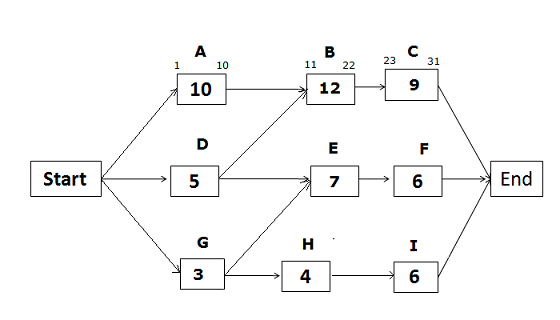
Early Start and Early Finish Dates for the path Start -> A -> B -> C -> End
Early Start of activity A = 1 (Since this is the first activity of the path)
Early Finish of activity A = ES of activity A + activity duration – 1 = 1 + 10 – 1 = 10
Early Start of activity B = EF of predecessor activity + 1 = 10 +1 = 11
Early Finish of activity B = ES of activity B + activity duration – 1 = 11 + 12 – 1 = 22
Early Start of activity C = EF of predecessor activity + 1 = 22 +1 = 23
Early Finish of activity C = ES of activity C + activity duration – 1 = 23 + 9 – 1 = 31
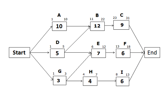
Early Start and Early Finish Dates for the path Start -> D -> E -> F -> End
Early Start of activity D = 1 (Since this is the first activity of the path)
Early Finish of activity D = 1 + 5 – 1 = 5
Early Start of activity E = EF of predecessor activity + 1
Since the Activity E has two predecessor activities, the activity with the greater Early Finish date is selected. As per calculations, Early Finish of activity D is 5, and Early Finish of activity G is 3.
Therefore, the Early Finish of activity D is selected to find the Early Start of activity E.
Early Start of activity E = EF of predecessor activity + 1 = 5 + 1 = 6
Early Finish of activity E = 6 + 7 – 1 = 12
Early Start of activity F = 12 + 1 = 13
Early Finish of activity F = 13 + 6 -1 = 18
Early Start and Early Finish Dates for the path Start -> G -> H -> I -> End
Early Start of activity G = 1 (Since this is the first activity of the path) Early Finish of activity G = 1 + 3 – 1 = 3
Early Start of activity H = 3 + 1 = 4 Early Finish of activity H = 4 + 4 – 1 = 7
Early Start of activity I = 7 +1 = 8 Early Finish of activity I = 8 + 6 – 1 = 13
Calculating Late Start (LS) and Late Finish (LF)
After calculating Early Start and Early Finish dates of all activities it is time to calculate the Late Start and Late Finish dates.
Late Finish of the last activity in any path will be the same as the Last Finish of the last activity on the critical path, because no activities can be continues once the project is completed.
The formula used for Late Start and Late Finish dates:
Late Start of Activity = Late Finish of activity – activity duration + 1
Late Finish of Activity = Late Start of successor activity – 1 To calculate the Late Start and Late Finish backward pass is used; that is calculations are started from the last activity and move back towards the first activity.
Late Start and Late Finish Dates for the path Start -> A -> B -> C -> End
On a critical path, Early Start, and Early Finish dates will be the same as Late Start and Late Finish dates.
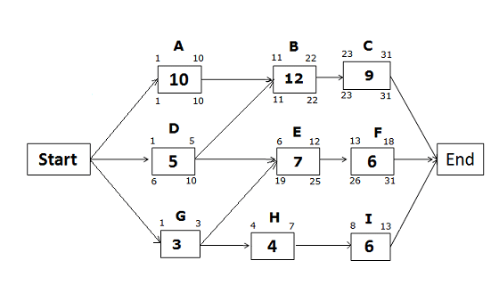
Late Start and Late Finish Dates for the path Start -> D -> E -> F -> End
Late Finish of activity F = 31 (because no activity can cross the project completion date)
Late Start of activity F = LF of activity F – activity duration + 1 = 31 – 6 +1 = 26 Late Finish of activity E = LS of successor activity – 1 = LS of activity F – 1 = 26 – 1 = 25
Late Start of Activity E = LF of activity E – activity duration + 1 = 25 – 7 + 1 = 19
Late Finish of activity D = LS of successor activity – 1
Looking at the network diagram, Activity D has two successor activities, B and E, where the activity with the earlier Late Start date is selected. Here, Late Start of activity B is 11, and Late Start of activity E is 19.
Therefore, activity B is selected as it has the earlier Late Start date.
Hence, Late Finish of activity D = LS of activity B – 1 = 11 – 1 = 10
Late Start of Activity D = LF of activity D – activity duration + 1 = 10 – 5 + 1 = 6
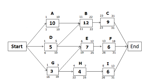
Late Start and Late Finish Dates for the path Start -> G -> H -> I -> End
Late Finish of activity I = 31 (because no activity can cross the project completion date)
Late Start of activity I = 31 – 6 + 1 = 26
Late Finish of activity H = 26 – 1 = 25 Late Start of activity H = 25 – 4 + 1 = 22
Late Finish of Activity G = 19 – 1= 18 (Late start of activity E is chosen instead of H, because the Late Start of activity E is earlier than the Late Start of activity H) Late Start of activity G = 18 – 3 + 1
References
1. [1]
