HAZOP method, deviation analysis
The Hazard and Operability analysis (HAZOP) was developed by Imperial Chemical Industry in 1963. At first, it was established for chemical industries, in order to evaluate risks related to the possible deviations of a project. HAZOP is a systematic and structured method mainly used during the first deign produce. It is also regularly updated during the operating stage of the plant. The main theory assumes that deviation forms are triggered by the operating design and bring about risky events. This method enables to analyse possible deviations of a plant, their causes and consequences in order to mitigate risks. The plant’s operating parameters (pressure, temperature…) are associated with guide words (more, less, no for instance) so that risks can be revealed and quantified. As a consequence, the plant is reviewed in a safer, more reliable and more efficient way.
Part of a project’s risk management, this method optimises resources and brings about financial benefits to the plant’s owner (and operator). It highlights which control and safety systems are really required to the plant. The quickest HAZOP’s recommendations are applied in the design process, the most are the benefits. Nowadays many companies use this method to enhance their project management. It is particularly well suited to systems that employ material and energy flows.
History
HAZOP was initially thought for reviewing a new phenol plant design. The Heavy Organic Chemicals Division of the Imperial Chemical Industry (British and international company) conceived this method in 1963. At the beginning, it was based on a critical examination studying the alternatives of a system. Later, the method’s focus was altered in order to study system’s deviations after producing the first detailed design of the plant. The operability study method was created.
In 1977, ICI published a guide of this method officially named HAZOP. Since that date, the deviation analysis process has been applied in many projects from various types of company. Discussions and research have highlighted its usefulness in project management, but they have also unveiled some limits.
When to perform this method
The Hazard and Operability Analysis should be performed when the project members aim to check a design or running instructions; to decide the location of a construction; to decide whether to buy a piece of equipment; to obtain a list of questions to put to a supplier; or to improve the safety of existing facilities. Even though HAZOP is commonly used after the first design is complete, it can be applied while the system is operating. The main domains using this hazard analysis method are chemical, pharmaceutical, oil and gas companies.
This deviation analysis is best suited for assessing hazards in processes, equipment or facilities using energy and material flows. Risks related to a project can be assessed from at least three perspectives thanks to HAZOP:
- Design
- Assess the system design capability to answer the user specifications, and to be in line with safety standards and guidelines
- Identify system’s weaknesses
- Physical and operational environments
- Assess the environment of the system to ensure that the location is appropriate in terms of places, thermal constraints, material near the installation (and possible danger with the operation) etc.
- Operational and procedural controls
- Assess engineered controls, sequences of operations, procedural controls such as human interactions
- Assess different operational modes such as the start and the shutdown of the system, the normal operation, the unsteady states of some functions, the emergency shutdown
HAZOP Process
Team Members
A team performing HAZOP should be composed from four to height multidisciplinary members. The facilitator (chairperson) must be experienced with HAZOP to ensure that his team do not diverge from the procedure. The Responsible Officer and him select the HAZOP team members. These members are from various domains. They will share their knowledge and skills in order to achieve the HAZOP process.
The basic team is composed of:
- Chairperson
- He is an independent person with sufficient knowledge of HAZOP techniques. He doesn’t have any responsibility with the system on which HAZOP is performed, nor with the domain the system will be applied.
- Project engineer
- Process engineer
- He is usually responsible for the P&Id (explanation later) and the process flow diagram and development.
- Design engineer
- The design engineer is usually specialised in mechanical design, has been involved with the design of the system and will be concerned with the project cost.
- Instrument/electrical engineer
- He designs and select the control systems for the plant.
- Safety engineer
Depending on the process, the team may also be composed of:
- Operation manager
- Maintenance engineer
- Suppliers representative
Other specialists may also enhance the formation of the team if they are appropriate for the method. For instance, if the plant includes chemical processes, a chemical engineer would step up the identification of deviations related to the chemical process.
HAZOP Terminology
Before applying HAZOP it is important to know the accurate definitions of the used terms. The facilitator must ensure that his team members have the same terminologies. This agreement on terminologies avoids assessment mistakes generated by misunderstanding.
- Part
- Subsystem with a specific intent/function (interest in the function needed for the system, not in safety elements)
- Element parameter
- Physical or chemical property associated with the process. Includes general terms such as
- Guide words
- Set of 10-12 words triggering the deviation
- Deviation
- Departures from the intention which are discovered by systematically applying the guide words to process parameters (e.g. "more pressure")
- Cause
- Reasons why deviations might occur. Once a deviation has been shown to have a credible cause, it can be treated as a meaningful deviation. These causes can be hardware failures, human errors, an unanticipated process state (e.g. change of composition), external disruptions (e.g. loss of power), etc.
- Consequence
- Results of deviations (e.g. release of toxic materials). Minor consequences unrelated to the study objectives are not considered.
- Safeguards
- Engineered system or administrative controls to prevent the causes or mitigate the consequences of deviations (e.g. process alarms, work procedures, vacuum valve)
- Actions required (or recommendations)
- Suggestions for design changes, procedural changes, or areas for further study (e.g. adding a redundant pressure alarm or reversing the sequence of two operating steps.
Preliminary HAZOP
Most of the time, systems require preliminary analysis. It helps to define the boundaries of the system the team is going to study. HAZOP’s scope is also discussed. For instance: The team wants to study a specific pump operating system taking water from a tank, and releasing it in a motor. They could only consider the pump system. If HAZOP’s boundaries also consider the pipes connecting to the pump, the tank before the pump and the motor’s system the scope is completely different and the deviation analysis will include other deviations than just the pump.
Some HAZOP analysis may have already been applied on similar systems. Accidents records and team members’ experiences enhance the deviation assessment. Therefore, the chairperson must organise meeting dates and supply the necessary resources for the meetings. He assures that all the team members have necessary information and tools for applying HAZOP. Tools and diagram define the system and allow the team to understand and overcome the operating system features, such as:
- Process Flow sheet and diagram (PFS or PFD)

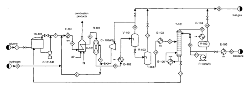
- It is a flowchart revealing the principal plant’s components. It is mainly used in chemical and process engineering, though its concepts can also be applied to other processes as well. Series of symbols and notations describe the process on the diagram (or sheet). PFD and PFS only show major components, and do not emphasise minor details as the P&ID.
- Piping and Instrumentation Diagram (P&ID)

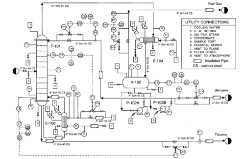
- This diagram displays all the minor details such as piping details and designations. It is more accurate than the previous diagram. It schematises the relationships between the functions of the piping. The Piping and Instrumentation Diagram is the last step in process design.
- Process calculations
- Process Data Sheets
- Instrument Data Sheets
- Interlock schedule
- Layout requirements
- Description of the process and provisional operating instructions
- Start-up and emergency shut down procedures
- Electrical area specification
- Standards used
- Maintenance procedures
Divide the system in parts
The plant must be divided in parts. This step of the HAZOP analysis is one of the most important and most difficult. The team members have to be careful not to divide too much the system in order to understand the function of each part and the links between the different parts. Referencing to the definition of the “part” is the best way not to diverge from HAZOP purpose.
Example 1:
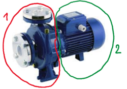
Figure 3: Pump example
A simple pump system composed of a power supply, receiving water from one side and releasing it by another. Part1 is the part of the pump in contact with the water and the pipes conveying water into the pump and releasing it after, whereas Part2 is power supply.
Study node and design intent
After dividing the system, the team chose study nodes from each part. Study nodes define the locations (on the piping and instrumentation drawings and procedures) on which the team will analyse the process parameters deviations.
For instance, if the part selected is a reactor composed of a pump, the pump is a study node. Study nodes could be a line, a vessel, a valve, a tank. The choice of study nodes depends on the chosen scope of HAZOP. If the team decided to analyse a pump in detail, the study nodes may be the power supply and the part in contact with water. If the system is built with a tank, pumps, valves, a motor, pipes, and many other items, the pump could be considered as only one study nodes and not be defined in two parts. The scope and the division of the parts of the system lead to the study nodes choices.
When a study node is selected, its design intent is clarified. The design intent is the description of how the system is expected to behave while it is studied. It is a qualitative estimation of the system activity and a quantitative estimation of the process parameters. Regarding the objective of HAZOP: knowing all the deviations of a plant in order enhance it, the knowledge related to the study node design intent is fundamental. Once the design intent is defined the team can select the process parameters and start to think about their deviations.
Select a process parameter
The most usual process parameters are:
- Flow
- Temperature
- Pressure
- Level
- Agitation
- Mixing
Other examples of process parameters:
- pH
- Composition
- Addition
- Separation
- Reaction
- Control
- Mixing
- Particle size
- Viscosity
- Time
- Start/Stop
- Transfer
- Speed
- Measure
- Communication
Parameters are associated with guide words in order to spot the possible deviations of the study nodes. Each study nodes are characterized by specific process parameters.
Example 1 (continuation of the pump): The first part of the pump (where water is flowing) takes into account water’s FLOW and the PRESSURE. Example 2: Some tank’s process parameters could be PRESSURE in the tank and LEVEL (because the volume of the tank is limited and a minimum level can be needed in some cases).
Apply a guide word
The choice of the guide words is relevant for detecting faults and operability problems. Those guide words are related to previous process parameters. They are estimated during the normal system operation, as well as during its start and its shutdown. The table below show examples of guide words and their common meanings.
| NO or NOT | Complete negation of the design intent | ||
|---|---|---|---|
| MORE | Quantitative increase | LESS | Quantitative decrease |
| AS WELL AS | Qualitative modification, increase | PART OF | Qualitative modification decrease |
| REVERSE | Logical opposite of the design intent | OTHER THAN | Complete substitution |
| EARLY | Relative to the clock time | LATE | Relative to the clock time |
| BEFORE | Relative to order or consequences | LATER | Relative to order or consequences |
When a process parameter is combined to a guide word it brings about deviations. For instance:
FLOW + NO = no flow
MORE + PRESSURE = High pressure ’’’Example 1’’’ (continuation of the pump): The flow of the part 1 of the pump can be related to the guide words: no, more, less, reverse
Determine possible causes and consequences of the deviation
Deviations may be triggered by various causes, such as:
- Insufficient outputs
- Valve closing
- Obstruction, clogging, foreign material
- Undesirable liquid input
- Temperature or pressure variation
- Operation error
- Sensor failure, computer failure, actuator failure, valve failure, set point error
- Excessive valve opening
- Insufficient supply
- Leak toward the outside
- Abnormally high density
- Vaporization or evaporation
- Maintenance error
- Human errors
The multidisciplinary team exchange their knowledge related to the system to establish an exhaustive list of possible causes and consequences of a deviation. One deviation can be triggered by multiple events, and may bring about various consequences and level of consequences (high, medium or low impact). Deviations bring about dangerous phenomena such as fire, explosion, toxic dispersion, system shutdown, non-achievement of the system purpose.
Recommend actions and safeguards
There are five types of safeguards:
- Identify the deviation
- Compensate for the deviation
- Prevent the deviation for occurring
- Prevent further escalation of the deviation
- Relieve the process from the hazardous deviation
The protection, detection and indicating mechanisms are part of safeguards. Their efficiency is taken in account in the estimation of the risk triggered by the deviation. Therefore, they can be improved or replace for safer, more efficient and more reliable devices.
Record information
Application examples
Advantages and limits
References
FLAUS, Jean-Marie. Risk analysis, Chapter 10: Deviation analysis using the HAZOP Method.
RAUSAND Marvin and HØYLAND Arnjolt. System Reliability Theory: Models, Statistical Methods, and Applications. Wiley 2nd Edition. January 2004
CLIFTON A. ERICSON II. Hazard Analysis Techniques for System Safety. John Wiley & Sons, 2016
NSW Government. HAZOP Guidelines, Hazardous Industry Planning Advisory Paper No 8. January 2011. www.planning.nsw.gov.au
MANCA, David. BFD, PFD, P&ID. Power point Lab 7 of “Process Systems Engineering” Politecnico di Milan. Last modification: 26 November 2014. Last view: 22 September 2017. pselab.chem.polimi.it
PQRI. Manufacturing Technology Committee –Risk Management Working Group. Risk Management Training Guides. Last modification: 3 Decembre 2015. Last view: 22 September 2017. http://pqri.org/wp-content/uploads/2015/08/pdf/HAZOP_Training_Guide.pdf
DAS, Idrajit. HAZOP ANALYSIS. Last modification: 3 March 2012. Last view: 22 September 2017. https://fr.slideshare.net/AnandKumar87/hazop-analysis
