Fishbone Diagram for Root Cause Analysis
Abstract
The major cause of uncertainty in organizations is risk. It is crucial to be able to identify those risks and manage them before it can have an impact on the organization’s objectives. Project Risk Management in organizations includes the processes of identifying possible risks, analysing those risks and then responding to them to maintain the objectives. The Fishbone diagram, also known as the Ishikawa diagram or the cause-and-effect diagram. was created by Kaoru Ishikawa in the 1960s. It is a visual tool used in Project Risk Management to identify the possible causes to a problem or effect with the practice of brainstorming. The shape of the diagram resamples the side view of a fish skeleton, hence the name Fishbone diagram [1]. The Fishbone diagram is highly visual and sorts ideas into useful categories and can be helpful in identifying areas for improvement and possible causes that might not be considered using other tools. This article will examine the use of the Fishbone diagram in Risk Management, an overview of the tool and a step-by-step guide to develop a Fishbone diagram, including models and other tools that can be combined in the process. The article also describes the significance of Risk Management in all Projects and the importance of knowing the risks for further analysation.
Contents |
The Big Idea: Fishbone Diagram
The Fishbone diagram, also known as cause-and-effect diagram or Ishikawa diagram, is a technique for root cause analysis and was invented by Kaoru Ishikawa, an engineer from Japan in the 1960s. The technique was then published in his book, Introduction to Quality Control, in 1990. Kaoru Ishikawa also defined the 7 quality management tools. He did not invent them all but was the first to combine them all in order to solve problems. The Fishbone diagram is commonly used in product designing or quality defect prevention to find the probable causes and identify potential factors that cause an overall effect. A problem or effect to the organizations objectives is stated and the goal of the Fishbone diagram is to identify all factors to that problem/effect and all causes to those factors. There can be more than one cause and one effect in risks and the diagram will assist in identifying those possible causes and help the organization identify the root cause of the problem or effect. When all root causes have then been removed, the problem is solved. According to the PMBOK® Guide the technique of The Fishbone Diagram is used in both the Manage Quality process and the Control Quality process [2] (p.293, 304), but the tool can also be used to identify the risks associated with a project. In Risk Management, The Fishbone diagram is used in risk identification to identify the many potential causes (root cause analysis) for an effect or problem and can be practical in sorting ideas into useful categories through brainstorming sessions [3]. Brainstorming is a tool that is used in risk management to gather comprehensive information about the risk/problem, both individual risks and risks that affect the project as whole. Brainstorming can be identified as free-brainstorming or brainstorming session where some structure is set beforehand. The Fishbone diagram is most often done in teams, and the discussion is set up as a structure using brainstorming to identify the problem or effect and the factors and causes to that problem. Brainstorming does not give solutions to the risk itself rather identifies the risk and gives a good idea what risks could arise within the project [2] (p.414).
Risk Management is the process of identifying, monitoring and managing the potential risks to all levels of the organization, from portfolios through programs, projects, and operations. Uncertainty in organizations is inevitable but risk management can provide information to limit the impact of uncertainty to the organization objectives. Individual risk can have a positive effect and a negative effect on objectives and is described as an uncertain event or condition. To assess how serious the risk is to the organization they need to consider both uncertainty, often described as probability, and the effect, often referred to as impact, on objectives [4]. Identifying risks from risk-related features is important. “Causes are events or circumstances that currently exist or are certain to exist in the future, which might give rise to risks. Effects are conditional future events or conditions that directly affect one or more objectives if the associated risk occurs” [4] (p.11).
Risk Identification is one of the processes in Risk Management. In Project Risk Management the focus is on anticipating the, and with management increase opportunities and decrease threats that could impact the success of the project [4] (p.57). Risk Identification is described as “The process of identifying individual project risks as well as sources of overall project risk, and documenting their characteristics” [2]. There are two main risks that arise within every project, which have to be concerned in each project together or as individual risk(s). These are Individual project risk and Overall project risk. Both these risks can have positive or negative outcomes for the project [2] (p.397). Individual project risk is an uncertain event or condition within the project and if it occurs it can have either a positive or a negative outcome. The objective of project risk management is to find the positive outcomes and minimize the negative outcomes. Unmanaged threats may result in delay, extra cost, bad performance overall and loss in reputation. While the Positive outcomes can be opportunities which can lead to great benefits such as reduced time, less cost and increased performance [2] (p.397). Overall project risk is the effect of uncertainty on the whole project. This can come from all sides of the project, including individual risk and is the perception from stakeholders to the implications of variations in the project. The overall project risk can also have either a positive or negative outcome. The objective of management of overall project risk is to keep the exposed risk within acceptable range and drive the positive outcome which can benefit the project overall [2] (p.397). The main advantages for using the Fishbone diagram are that it is highly visual, quickly identifies the risks associated within the project itself and clearly stated the main problem or effect. It also has good visualization properties for individuals who enter the project later on and for presenting to stakeholder. The technique is also easy to use and both simple to learn and apply.
Application: Fishbone Diagram
In this section a step-by-step guide to develop a Fishbone diagram in a team setting is described. The section also includes models and methods that can be helpful to use in conjunction with the Fishbone diagram.
Step 1: Identify the problem
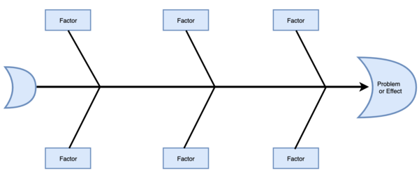
The first step for the team is to define a problem or effect that the team wants to analyse. For a successful Fishbone diagram, it is critical to define the problem correctly. Have the team think, consider and identify who is involved, what the problem is, and when and where it occurs. When the problem has been identified it is written in a box on the center right-hand side with a horizontal arrow running to it, e.g., on a large sheet of paper or whiteboard. It is also possible to write the problem statement on the center left hand side, whichever you prefer. Resembling a head and spine of a fish, this layout, will give you space to develop ideas in the next steps [5].
Step 2: Work out the Major Factors Involved
In the next step the team identifies the factors involved in the problem or effect. In this step it can be helpful to use brainstorming techniques as described above. An example of these factors are Site, Task, People, Equipment and Control. To achieve the best outcome, try to identify as many of these factors as possible. Then, they are written down as branches off the spine of the diagram and resemble the bones [5].
Useful models
To help in this step of the diagram teams often use common models of factors, is applicable, to start the process. The models here below are set up for problems within a specific aspect but the factors can also be relevant to use in other cases. The factors mentioned in each model below are added as branches to the model as described in step 2. 5M used in the Fishbone diagram - mainly for Manufacturing [6].
- Method
- Mother Nature
- Man
- Machine
- Materials
This method is also known as the 6 M method with the addition of Measurement.
8Ps used in the Fishbone diagram - mainly for Product Marketing [6]. Product
- Place
- Price
- People
- Promotion
- Physical Evidence
- Process
- Performance
4Ss used in the Fishbone diagram - mainly used in the service industries [6].
- Suppliers
- Surroundings
- Systems
- Skills
Step 3: Identify Possible Causes
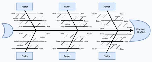
In the third step, the team identifies the possible causes associated to each factor determined in the previous step. Again, the team should use brainstorming techniques to identify these causes, and if the problem or effect is large/complex it may be effective to also break down the causes into sub-causes. Have the team think about “Why does this happen?”. Then, the causes and sub-causes are written down as lines coming off each factor branch. If the cause applies to more than one factor it can be added to several branches [5]. In the example below the problem is stated: „12% of product fails inspection for screw alignment“. The model of 6M‘s is then used to identify the factors in this manufacturing problem, and the identified causes by the team are: [7] Method: Instructions were not clear and/or Instructions were not followed Man: Employee has not bee trained and/or Employee fatigue Machine: Tools are worn and/or Tools are not the right size Materials: Screws were worn and/or Screws were the wrong size Measurement: The correct gauge was not used to measure the parts and/or The gauge was not zeroed before measuring the part (Mother Nature was not used in this Fishbone diagram example)
The 5 Why's
Another tool used for root cause analysis is the „5 Why‘s“ method. It can be combined with the Fishbone diagram and be helpful in identifying the causes to each factor of the stated problem. The name refers to the practice of the team repeatedly asking themselves „Why?“ and with that identify any causes related to the problem. Even though the name states 5 why‘s you might have to ask the question fewer or more times than that to identify the root cause. All the answers from this technique, from all members of the team, are then included in the Fishbone diagram [8].
Step 4: Analyse Your Diagram
At this stage of the Fishbone diagram all the possible causes that the team has been able to identify should be shown with the problem or effect. Then, the team can look into the causes and identify the ones that they assume are most likely to have an impact, and inspect them further, e.g., by conducting a survey [5]. The team can also analyse the diagram by inspecting the causes that appear the most often on the diagram. If a similar cause is identified in multiple factors, e.g., lack of training, it is probably having an major impact to the problem or effect and prioritising that cause in future solution implementation is advisable.
Risk Analysis
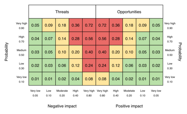
In Project Risk Management the risk is evaluated by considering the amount of impact it has on the project objectives and the probability of occurrence. The focus of this process is on high-priority risks and therefore it can be useful in the last step of analysing the Fishbone diagram. The data representation tool: Probability and impact matrix can be useful for this process where the probability of occurrence for each risk is mapped on a grid as well as the impact it has on the project objectives if it would happen [2]. (p.425).

Limitations
Like all other tools the Fishbone diagram has some limitations. How successful the diagram is depends largely on the team involved in the process. If team members are not skilled and experienced the chance of an effective and informing results is not great. But still, even with skilled and experienced team members the diagram does not single out the root cause of the problem or affect analysed. All of the identified causes need to be analysed and some of them might even have little effect on the problem. If the problem or effect is too complex the Fishbone diagram can end up chaotic and difficult to analyse what exactly is the root cause to the problem. The brainstorming part of the diagram also has some limitations. With brainstorming the diagram is based on opinions rather than evidence. It is a time-consuming process and often not all team members contribute equally to the process. Overall, the results of the Fishbone diagram clearly identify the possible causes of the problem but does not solve the problem. Other tools or methods are needed to further analyse each cause and solve the problem itself.
Annotated bibliography
Cause and Effect Analysis using the Ishikawa Fishbone & 5 Whys This article provides an overview of the Fishbone diagram, the steps involved combined with the 5 Why's method.
Guide to the Project Management Body of Knowledge This book provides thorough description of Project Management and information on Risk Management and all processes involved.
Cause and Effect Analysis This article provided a good step-by-step guide to the Fishbone diagram tool.
Standard for Risk Management in Portfolios, Programs, and Projects This book addresses Risk Management in Portfolios, Programs, and Projects.
References
- ↑ Quality tools: fishbone diagram. Design Buildings Wiki. https://www.designingbuildings.co.uk/wiki/Home
- ↑ 2.0 2.1 2.2 2.3 2.4 2.5 2.6 2.7 Project Management Institute, Inc.. (2017). Guide to the Project Management Body of Knowledge (PMBOK® Guide) (6th Edition). Project Management Institute, Inc. (PMI). Retrieved from https://app.knovel.com/hotlink/toc/id:kpGPMBKP02/guide-project-management/guide-project-management
- ↑ Fishbone Diagram. ASQ. https://asq.org/quality-resources/fishbone
- ↑ 4.0 4.1 4.2 Project Management Institute, Inc. (PMI). (2019). Standard for Risk Management in Portfolios, Programs, and Projects - 7.1.3 Project Risk Response Strategies. Project Management Institute, Inc. (PMI). Retrieved from https://app.knovel.com/hotlink/pdf/id:kt011VVUA4/standard-risk-management/project-risk-response
- ↑ 5.0 5.1 5.2 5.3 Cause and Effect Analysis. MindTools. https://www.mindtools.com/pages/article/newTMC_03.htm
- ↑ 6.0 6.1 6.2 A complete Guide for Fishbone Diagram (Ishikawa Diagram).EdrawMax Online. https://www.edrawmax.com/fishbone-diagram/
- ↑ Fishbone (Ishikawa) Diagram Template for Root Cause Analysis. (2018). Tulip Interfaces, Inc. https://tulip.co/blog/lean-manufacturing/fishbone-ishikawa-diagram-for-root-cause-analysis/#:~:text=Here%2C%20the%20causes%20are%20categorized,%E2%80%9Cribs%E2%80%9D%20of%20the%20fish.
- ↑ Cause and Effect Analysis using the Ishikawa Fishbone & 5 Whys. City Process Management. http://www.cityprocessmanagement.com/Downloads/CPM_5Ys.pdf


