Network Planning
Contents |
Abstract
The success of a project's realization depends heavily on the effectiveness of the planning phase. This article will present how to use network planning in project management, which can be very challenging, and requires careful planning, managing, and controlling. The ability to break down work and segment it into different assignments can be critical for project success. Having a comprehensive plan can explain the project's complexity and keep it on track [1]. Network planning is a common term for methods where projects are studied as a series of interrelated activities to plan, manage, and control projects [2].
According to Guide to the Project Management Body of Knowledge, project schedule management includes various processes required to manage the project's timely completion. These processes refer to, among other things, how to sequence activities and estimate activities duration. Moreover, they include developing and controlling the schedule. Network planning methods help in this processing. The main objectives of network planning are determining the project duration and the Critical Path. Moreover, find out how to speed up a project if that becomes necessary. As a result, it is a basis for scheduling [3].
The most well-known network planning techniques are the Critical Path Method (CPM) and the Program Evaluation and Review Technique (PERT). These methods include describing each of the activities involved in the project, the order in which must carry out the activities, and the activities carried out in tandem with other activities. Using network planning methods results in showing activities that can be completed simultaneously and increases efficiency. Moreover, it helps in decisions making and saves time, and therefore decreases cost. Conversely, creating it uses merely estimates, which may be inaccurate. Furthermore, large scale projects are often complex and detailed, and thus performing network planning on them, can be time-consuming [2].
The focus of this article will be introducing network planning and describing different methods of it. Moreover, identify how to apply network planning techniques to project management and choose the right method for various projects. Finally, this article will describe the limitation of network planning.
Why Use Network Planning in Project Management?
History
Network planning methods were first developed in the late 1950s. The most known network planning techniques are the Program Evaluation and Review Technique (PERT) and Critical Path Method (CPM), which were also the first methods developed. Initially, PERT was built to prepare and control the Polaris rocket, an extensive project involving thousands of operations, using more than 3,000 contractors. As a result, the project’s duration was reduced by two years. Many government contracts also involve the use of PERT or a similar technique because of its effectiveness. CPM was designed initially for the preparation and coordination of chemical plant maintenance programs [4].
Description of Network Planning in Project Management
Network planning can research various issues such as project scheduling, risk analysis, cost minimization, or net present value maximization. Therefore, it can find the most appropriate balance between risk, quality, length, and cost. Moreover, using network planning in project management allows project teams to visualize all the tasks that need to be done during a project’s lifecycle. It also provides essential context, such as length of the job, sequence, and dependence on the project schedule. Furthermore, it helps to find the critical path, slack, and max float, among other things [2].
From the complexity perspective, the central part of ISO 21500 discusses project and project management. It suggests structural, technical expertise to be implemented in a particular sequence in the form of activities. Thus, projects operate smoothly, effectively, and efficiently. Moreover, activities related to complexity are linked to the planning processes and involve the functions necessary to manage and control various project-related activities. The primary purpose of network planning in project management is to aid in the planning, managing, and controlling of projects [1].
Network planning is a sequential categorization of the activities involved in the project's execution, accompanied by a graphical presentation of the actions required for the project as a whole. Therefore, network planning is a distributed model of work to be done in a project. A hierarchy of interdependent job elements, which are processes, tasks, and activities, is sequenced and prioritized to identify and describe the overall project effort. Typically, the project network is constructed and built using charts and hierarchical diagrams or often termed project network diagrams [5].
Each terminal element represents an operation at the lowest level of the work breakdown structure (WBS) related to a work package. However, although the WBS does not attempt to decide the sequence of events or the length of any activity, the network planning diagram attempts to determine the series of activities that take place and the other activities (if any) on which the activity depends. When conducting network planning diagram, there is a range of techniques used. Critical Path Management (CPM) and the Project Evaluation and Review Technique (PERT) are some of the most widely used methods. Every terminal element (or activity) is represented by a node on a graph in some techniques, while it is characterized by an edge in others (the line connecting two nodes). Only one path for every terminal element must lie through the network [6].
Multiple sequences of activities are included in the network planning that specifies one or another aspect of work, for example, a process or phase. The main criterion for the network planning efficiency is that each sequence of activities should have a finite and measurable outcome and never contain circular references. If there is a circular reference in an operation chain, it creates a closed-loop, resulting in an endless cycle [5].
A network planning diagram allows the project manager to assess a project's most likely sequence of events and provides the basis for a practical project schedule. It will enable the project manager to measure the total duration needed for the project, determine the order in which tasks need to be completed, and highlight those tasks vital to the project's timeline. Once the WBS is complete, the project manager will have a list of tasks at different decomposition stages to accomplish the project's goal. To allow a schedule to be generated, the project manager now decides the task dependencies and each task's length. Project management software is now available to perform the scheduling for project managers, measure the total time needed to complete the project, and define the schedule's critical path. Merely what project managers have to do is determine each task's length and consider any task dependencies. Based on the data they provide, the program can generate network activity charts [6].
Application
It is important to break down projects into smaller activities for projects to become achievable. Furthermore, to coordinate these interdependent activities and finally, adapt the project and respond to changes. When the project has been broken down into smaller pieces and the activities defined, the scheduling of it can begin [1]. In project management, there are two primary types used when drawing network diagrams, which are the Arrow Diagramming Method (ADM) and the Precedence Diagramming Method (PDM) [7].
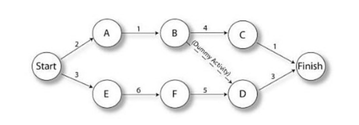
The arrow diagramming technique (ADM) refers to a schedule network diagramming technique in which arrows represent schedule activities within a specified project. The arrow's tail or base defines the start of the operation in the schedule. The pointed end of the arrow illustrates the endpoint of a selected process within the schedule. The duration of the arrow will loosely reflect the time between. The points to which these planning operations are connected are referred to as nodes. To illustrate the sequence or order in which these activities should occur, the relation of these schedule activities is performed. This link point, or node, is typically represented by a small circle or sphere. An operation with a length of zero can be seen in the ADM graph below. These operations are referred to as dummy operations and are usually represented using dotted lines. Dummy activities express dependencies between tasks. The activity B-D in the below diagram is a dummy activity. An example of why a project manager might need a dummy activity is if activity C is about tiling a floor. It can only start once the concrete is poured (Activity B) and the permits are gotten in activity D. In contrast, activities B and D are not directly linked, the project manager needs to draw a dummy activity between B and D to demonstrate that C is dependent on D being finished. Moreover, there is also not possible for an ADM chart to encapsulate lead and lag times without new nodes and activities being implemented [7][8].
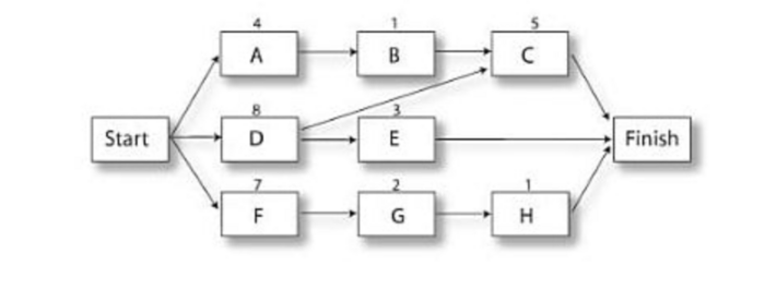
The precedence diagramming method (PDM) refers to a selected project management technique. The project manager employs a schedule network diagramming technique to graphically represent any known and preexisting schedule activities via the utilization of boxes (which also can be mentioned as nodes). Once all of these basic schedule tasks have been graphically displayed in this box or node format, all of the individual boxes are connected by using a line describing any logical relationship that is found to occur. The fundamental and most important advantage of using the precedence diagramming system's style methodology is that it helps the project manager view all plan tasks and their relationships with each other rapidly and efficiently [7][8].
Networks flow from left to right in both arrow diagrams and precedence diagrams. Each activity is marked with a unique name, and once all its previous activities are complete, the activity may start. For example, as per the node diagram activity shown above, activity C can not begin until activity B and activity D has been completed. The nodes for start and stop should be distinctive [8].
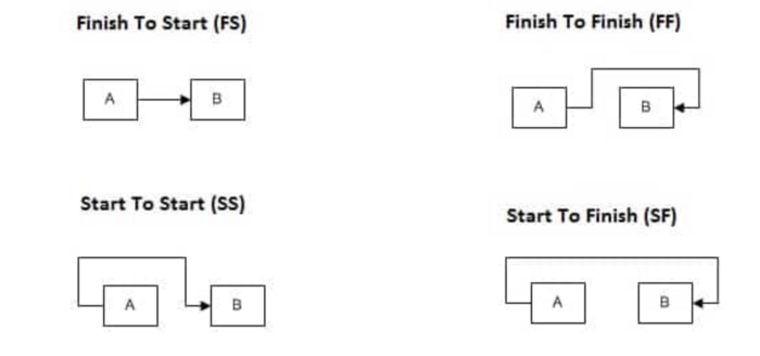
In network diagrams, four types of dependencies are primarily depicted. They are Finish to Start (FS), Finish to Finish (FF), Start to Start (SS), and Start to Finish (SF). It is possible to represent these four types of dependencies as shown below [8].
Finish to Start (FS): The next activity (successor) in this relationship cannot be initiated before the first one (predecessor) is finished. In network diagrams, this is the most common form of the dependency used. An example of this kind of dependency is that it is impossible to begin floor tiling until the waterproofing is finished. In the ADM graph, the only relation between the nodes can be expressed by an activity that is of "finish to start" dependency [8]Cite error: Closing </ref> missing for <ref> tag
Cite error:
<ref> tags exist, but no <references/> tag was found


