The Failure Mode and effects analysis (FMEA) in product development projects
Every project faces uncertainties all along its life cycle. Dealing with risks is then a fundamental aspect for a successful project management: uncertainties can affect the possible outcomes and project effectiveness. Companies and industries across the globe are cutting costs and shortening development times [1]. Yet high reliability and impeccable safety are essential to customer satisfaction and financial viability. The risk management's objective is then to assure that uncertainty does not affect the project goals. This article aims to show how FMEA as a risk management tool improves reliability and safety while reducing warranty costs in the context of product development.
Contents |
Model description and procedure
The Failure Modes and Effects Analysis (FMEA) can be described as a systemized group of activities intended to identify and analyse:
- All potential failure modes of the various parts of the system
- The effects these failures may have upon the system
- How to avoid the failures, and/or mitigate the effects of these failures on the system
A failure mode is defined as the way in which a component, sub-system or system could potentially fail to perform its desired function[2].
FMEA is then a systematic technique of identifying, analysing and preventing product and process problems before they occur. The 3 most common types of FMEA are:
- Design FMEA is used to analyze product designs before they are released to production. It focuses on potential failure modes associated with the functions of the product and caused by design deficiencies[3];
- Process FMEA is used to analyze the new or existing processes. It focuses on the potential failure modes associated with both the process safety /effectiveness/efficiency, and problems with the functions of a product caused by the problems in the process [3].
- System FMEA is the highest level analysis of an entire system , made up of various subsystems. The focus is on system - related deficiencies, including system safety, system integration, interfaces or interactions between subsystems or with other systems, interactions with the surrounding environment, human interaction, service, and other issues that could cause the overall system not to work as intended[1].
Although the purpose, terminology and other details can vary according to the type of FMEA, the basic methodology is similar for all. To be successful, FMEA must be performed as team-based activity and it needs the right team of subject matter experts. Even the best engineers have blind spots and only a team composed of the right disciplines can provide the necessary input and discussion to ensure all concerns are surfaced and addressed [1]. This enables to tackle the risk analysis from different perspectives and then to reduce the possibility of non-considered risks appearance. The development procedure of an FMEA is divided into several subsequent steps:
The development procedure of an FMEA is divided into several subsequent steps:
- FMEA prerequisites
- System structure analysis
- FMEA worksheet
- Team review
- Corrective actions
FMEA prerequisites
The first step of the FMEA development includes the following tasks:
- Define the system to be analysed.
- System boundaries (which parts should be included and which should not).
- Main system missions and functions (including functional requirements).
- Operational and environmental conditions to be considered.
- Interfaces that cross the design boundary should be included in the analysis.
System structure analysis
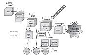
The aim of this step is to divide the system into manageable units, typically functional elements. The level of detail that we should break down the system will depend upon the objective of the analysis. Being FMEA a bottom-up approach, It can be also desirable to illustrate the structure by a hierarchical tree diagram in order to identify potential/known failure modes at one level and investigates the effect on the next sub-system level .
FMEA worksheet
FMEA uses a tabular method of presenting data, meaning the content of the analysis is visually displayed in a series of worksheet rows and columns[1].
For each system element (subsystem, component) the analyst must consider all the functions of the elements in all its operational modes, and ask if any failure of the element may result in any unacceptable system effect.
The definition of each column is presented in the sequence they are normally developed in a FMEA project, which correspond to the logical relationship between FMEA elements.
Columns explanations
For each system element (subsystem, component) the analyst must consider all the functions of the elements in all its operational modes, and ask if any failure of the element may result in any unacceptable system effect. The worksheets are divided into different columns:
(1) Item: A unique reference to an element (subsystem of components) is given. It may also be a reference to an identity number in a specific drawing, a so-called tag number, or the name of the element
(2) Function: functions of the element are listed. A checklist may be useful to secure that all the functions are considered
(3) Failure mode: for each function and operational mode (ex. of operational modes are idle, standby, running) of an element the potential failure modes have to be identified and listed. Note that a failure mode should be defined as a nonfulfillment of the functional requirements of the functions specified in (2).
(4) Potential effect of failure:
- On the subsystem: the effects each failure mode may have on other components in the same subsystem and on the subsystem as such (local effects) are listed.
- On the system function: the effects each failure mode may have on the system (global effects) are listed. The resulting operational status of the system after the failure may also be recorded, that is, whether the system is functioning or not, or is switched over to another operational mode. In some applications it may be beneficial to consider each category of effects separately, like: safety effects, environmental effects, production availability effects, economic effects, and so on.
(5) Severity: the severity of a failure mode is the worst potential (but realistic) effect of the failure considered on the system level (the global effects).
(6) Failure cause or mechanism: failure modes identified in (3) are studied one-by-one. Failure mechanisms (for example, corrosion, erosion, fatigue) that may produce or contribute to a failure mode are identified and listed. Other possible causes of the failure mode should also be listed.
(7) Occurrence: failure rates for each failure mode are listed.
(8) Current design controls (prevention)
(8) current design controls (detection): various possibilities for detection of the identified failure modes are listed. May involve diagnostic testing, different alarms, proof testing, human perception, etc. Example: Failure mode “fail to start” of a pump with operational mode “standby” is an example of a hidden failure.
(9) Detection: detection is a ranking number associated with the best control from the list of detection - type controls, based on the criteria from the detection scale. The detection ranking considers the likelihood of detection of the failure mode/cause, according to defi ned criteria.
(10) Risk priority number (RPN): a numerical ranking of the risk of each potential failure mode/cause, made up of the arithmetic product of the three elements: severity of the effect, likelihood of occurrence of the cause, and likelihood of detection of the cause.

(11) Reccommended actions - Risk reducing measures: possible actions to correct the failure, and restore the function or prevent serious consequences.
Team review
The main objectives of this step are:
- Decide whether or not the system is acceptable
- Identify feasible improvement of the system to reduce the risk. This can be achieved by reducing the likelihood of occurrence of the failure, reducing the effects of the failure, increasing the likelihood the failure is detected before the system reaches the end user.
Corrective actions
Risk may be reduced by introducing:
- Design changes
- Engineered safety features
- Safety devices
- Warning devices
- Procedures/training
FMEA in product development projects
Project life cycle
The project Management Institute (PMI) defines a project as “a temporary endeavour undertaken to create a unique product, service, or result. The temporary nature of projects indicates that a project has a definite beginning and end. The end is reached when the project's objectives have been achieved or when the project is terminated because its objectives will not or cannot be met, or when the need for the project no longer exists”.
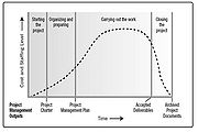
Every project passes through a series of phases all along its life, from the start to the closure: all these phases represent the project life cycle. While every project life cycle is determined or shaped by the specific nature, industry and technology employed by the specific organization, all projects can be mapped to the following generic life cycle structure[4]:
- Starting the project,
- Organizing and preparing,
- Carrying out the project work
- Closing the project
In this article, the specific case of new product development is analysed.
New product development (NPD) is the process by which an organization uses its resources and capabilities to create a new product or improve an existing one [5] .
Product development is seen as “among the essential processes for success, survival, and renewal of organizations, particularly for firms in either fast-paced or competitive markets”) [6]
Cite error:
<ref> tags exist, but no <references/> tag was found


