Location Based Scheduling
(→Annotated Bibliography) |
|||
| (116 intermediate revisions by 3 users not shown) | |||
| Line 1: | Line 1: | ||
| − | + | ''Developed by Bjarke Rahr Tanghus'' | |
| − | |||
| − | [ | + | [[File:Empire.png|thumb|'''Figure 1:''' LBS from the construction of <span class="plainlinks">[https://en.wikipedia.org/wiki/Empire_State_Building The Empire State Building]</span> Source: https://2build.wordpress.com/2015/02/03/aec-hackathon-nyc-recap/]] |
| − | + | ||
| − | + | ||
| − | + | ||
| − | + | ||
| − | + | ||
| + | '''The Location Based Scheduling (LBS)''' method has been developed to help '''project managers''' in the construction industry with workflows and planning. The main philosophy about LBS has been to create a tact in the construction projects by including both the time of an event and the location where event takes place. The different tasks in the projects need to proceed in the same flow to create a constant progression without wasting time. The method is visualized by a graphical tool based on a technique developed by <span class="plainlinks">[https://en.wikipedia.org/wiki/Karol_Adamiecki Karol Adamiecki]</span> in the early 20th century. <ref name="Optimizationofflowline"> Martinez, Natalia Rodriguez (2013). ''Optimization of Flowline Scheduling vs.Balanced Resources and Task Continuity''. Norwegian University of Science and Technology.</ref> <span class="plainlinks">[https://en.wikipedia.org/wiki/Karol_Adamiecki Karol Adamiecki]</span> developed a schedule tool named ''harmonogram''. This tool includes location as a key element in the scheduling, in contrast to the [[Gantt Chart]]. There has been previous examples of the application of <span class="plainlinks">[https://en.wikipedia.org/wiki/Karol_Adamiecki Adamiecki's]</span> concept. The construction work of <span class="plainlinks">[https://en.wikipedia.org/wiki/Empire_State_Building The Empire State Building]</span> was one of the first projects that used location as main unit of analysis. The results were ground breaking due to the fact that around 380 m2 were built per day of construction. The 102 levels were completed in 18 months with a significantly low number of accidents for its time and under the initially estimated budget. <ref name="Sacks"> Sacks, R. & Partouche, R (2009). ''Empire State Building Project: Archetype of "Mass Construction"'', Journal of Construction Engineering and Management, 136(6), 702-710.</ref> | ||
| − | + | The most common method in time and resource planning in construction is still today [[The Critical Path Method (CPM)]]. CPM has been the most dominating method since it was introduced in the late 1950s. It has been proved an effective method for time and resource planning of projects. Thus, some critique has been raised about the CPM-method in relation to construction projects, as it does not sufficiently support construction management during execution, nor does it create a continuous and thus economical flow of resources. | |
| − | + | The LBS method has been developed for the planning and management of workflows and could therefore be expected to be a viable alternative to CPM. The construction industry struggles with the subsequent delays and budget overruns and hopefully the LBS can help the industry meet these challenges. | |
| − | + | ||
| − | + | ||
| − | + | ||
| − | The LBS method | + | |
| − | + | ||
| − | + | ||
| − | + | ||
| − | + | ||
| − | + | ||
== About Location Based Scheduling == | == About Location Based Scheduling == | ||
| − | |||
| − | [[File:PMWheel.jpg|right| | + | [[File:PMWheel.jpg|right|345px|thumb|'''Figure 2:''' General content of project management <ref name="PMBOK"></ref>. Primary focus in this article is on schedule development. ]] |
| − | Location Based Scheduling is placed in the realm of '''Project Management'''. The main focus of the article is to describe LBS, a Project Time | + | '''Location Based Scheduling''' is placed in the realm of '''Project Management'''. The main focus of the article is to describe LBS, a '''Project Time Management''' tool, used by project managers in the construction industry. As shown in Figure 2 from ''Project Management Body of Knowledge'' <ref name="PMBOK"> The Project Management Institute (2008). ''A Guide to the Project Management Body of Knowledge (PMBOK ® Guide)'', 4th Edition. PMI Publications.</ref>, '''Project Time Management''' is a crucial part of a project managers scope. |
| − | The overall idea | + | The overall idea with LBS is to create a schedule that can be used as followed: <ref name="VurderingafLBS"> Andersson, N. & Christensen, K. ‘Location-based Scheduling: ''"Vurdering af LBS-metodens anvendelse i byggeprojekter"'', The Technical University of Denmark.</ref> |
| − | * The schedule should ensure that the main goal of the project is archived within the time | + | * The schedule should ensure that the main goal of the project is archived within the time, resource and qualitative framework applicable to the project. |
| − | * The schedule | + | * The schedule should work as an overview map of the project, showing the planned way from start to end. |
* The schedule serves as a basis for analysis and decisions regarding choice of production methods, materials and supplies and other resources. | * The schedule serves as a basis for analysis and decisions regarding choice of production methods, materials and supplies and other resources. | ||
| − | * The schedule serves as a communication tool to convey the structure of the production progress: what should be done when | + | * The schedule serves as a communication tool to convey the structure of the production progress: what should be done when, which resources should be used, in which order should the tasks be carried out. |
| − | * The schedule serves as an foundation for | + | * The schedule serves as an foundation for continuous following-up on the produced part of the project. Therefore, it can be used as a basis for identifying possible deviations and the consequences of these. |
| − | LBS is based on the fundamental planning elements: activities, resources and the link between them. In addition to this, LBS also uses | + | LBS is based on the fundamental planning elements: activities, resources and the link between them. In addition to this, LBS also uses -locations, critical room to manoeuvre, location based activity links and resource flow to name a few. A central part of LBS is to create the right flow through the project. The right flow ensures that the resources in the independent activities flow smoothly through the different locations of the project. A geographical location of the activities in the project is added in LBS. This makes it possible to identify ''where'' and ''when'' the different tasks should be carried out. Furthermore, it creates the possibility to draw the LBS-methods typical "Time/Place-Diagram" or "Flow-Line Diagram" (see Figure 3), which is the LBS-methods graphical representation. <ref name="VurderingafLBS"/> |
| + | |||
| + | ---- | ||
=== Flow-Line Method === | === Flow-Line Method === | ||
| − | Professor Shlomo Peer from Technion-Israel Inst. of Tech., Haifa, Israel, was one of the first contributors to the | + | Professor Shlomo Peer from Technion-Israel Inst. of Tech., Haifa, Israel, was one of the first contributors to the Flow-Line method. This method constituted a new way of displaying and handling activities in construction projects. One of Shlomo Peer's main points <ref name="Peer"> Peer, S (1974) ''Network analysis and construction planning'', Journal of the Construction Division-ASCE, 100(NCO3), p. 203–210</ref> was that scheduling and control in the construction industry should aim to complete the projects in the shortest possible time that is compatible within the financial limitations. The fastest time is not necessarily the most economical, nor is the relationship between available resources and construction time linear. Based on this statement, Shlomo Peer produced a construction planning process for the location-based methodology. The step is as follows <ref name="Peer"></ref>: |
| − | # Break | + | # Break the project down into constituent component processes. |
# Divide realization of these processes between adequate production crews. | # Divide realization of these processes between adequate production crews. | ||
# Define technological connections between the crews and activity categories. | # Define technological connections between the crews and activity categories. | ||
| Line 55: | Line 43: | ||
# Balance the progress of noncritical flow lines with that of the chosen critical one, aiming to achieve working continuity. | # Balance the progress of noncritical flow lines with that of the chosen critical one, aiming to achieve working continuity. | ||
# Within practical limits, check the possibility of shortening construction time by introducing planned breaks in continuity or changes in crew size. | # Within practical limits, check the possibility of shortening construction time by introducing planned breaks in continuity or changes in crew size. | ||
| − | # | + | # Analyse the entire process in terms of time and duration of activities and produce a plan. |
| − | When the eight steps above | + | When the eight steps above has been carried out, one can start producing the Flow-Line Diagram. |
==== Flow-Line Diagram ==== | ==== Flow-Line Diagram ==== | ||
| − | The Flow-Line Diagram is the graphic tool in LBS. The different activities are illustrated as lines in a XY-coordinate system. The Y-axis in the Flow-Line | + | The Flow-Line Diagram is the graphic representation tool in LBS. The different activities are illustrated as lines in a XY-coordinate system. The Y-axis in the Flow-Line Diagram is divided into the physical locations of the project. The X-axis indicates the timewise progress of the project. |
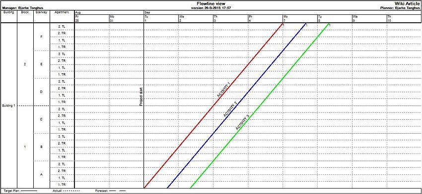
| − | The activities depicted as lines in the coordinate system. | + | The activities are depicted as lines in the coordinate system. The combination of axis displaying time and locations, gives an overview of ''where'' and ''when'' activities has to be carried out. The duration of each activity is seen at each location by the length of the flow-lines. The activities can be scheduled parallel to one another, so that there in this manner will be obtained an even flow and a stable rhythm of the construction. This results in, there being no days with numerous activities and other days with very few activities. The duration of each activity is estimated by the project manager in terms of man-hours needed to execute the task. The estimation is based on a combination of quantitative data in form of quantities from the tender list and qualitative experience. The actual time planned for the activity varies in proportion to the allocated resources; this is visualized by the slope of the Flow-Lines. A rapid and short activity has a steep line, while a slow and time-consuming activity has a rather flat line. In Figure 3, activity 1 and 3 have a duration of one day, and activity 2 a duration of eight days. |
| − | |||
| − | + | [[File:LBSeksempel.JPG|center|thumb|850px||'''Figure 3:''' One long and two slow activities in a Flow-Line Diagram]] | |
| − | + | ||
| − | [[File:Hierarchy_in_Vico.JPG|right| | + | To create the Flow-Line Diagram, the locations of the project has to be decided. |
| + | |||
| + | ====Identifying the locations==== | ||
| + | [[File:Hierarchy_in_Vico.JPG|right|180px|thumb|'''Figure 4:''' Hierarchical Breakdown Structure]] | ||
| − | Identifying the | + | Identifying the locations of the project is a central element in the LBS-method. The projects hierarchical location structure (e.g building - block - stairway - apartment) is shown in the Flow-Line Diagram Y-axis. Each activity in the schedule is planned in relation to a location. To decide the hierarchical location structure a Location Breakdown Structure (LBS) is performed. This hierarchical breakdown structure can be compared with the [[Work Breakdown Structure (WBS)]], used in activity-based scheduling. The logic behind LBS is that the sum of locations on a lower level counterbalances a location on a higher level, as shown in Figure 4. As activities can correspond to different levels of the hierarchy, one needs to make the following considerations when determining the location hierarchy:<ref name="VurderingafLBS"/> |
| − | * | + | * Which is the smallest site where repetitions will occur in the project? |
| − | * | + | * Which is the smallest locality in which material resources for current activities can be distributed? |
| − | * Which is the largest locality in which there is only room for the execution of the current activity | + | * Which is the largest locality in which there is only room for the execution of the current activity? |
| − | E.g. preparation of the construction site | + | E.g. preparation of the construction site would in Figure 4 corresponds to the building level in the hierarchy, whereas installation of kitchens would correspond to the apartment level in the hierarchy. |
| − | + | ---- | |
| − | + | ===Optimization using Flow-Line Diagram=== | |
| − | + | When the different locations are identified and the internal hierarchy established, then the activities can be plotted. The optimization is generated through resources and activity-links. The activity-links help reduce the length of the project, as the graphical representation in the Flow-Line Diagram secures that multiple activities can be scheduled simultaneous. This without causing an accumulation of resources at a certain location. Other traditional scheduling methods and tools, like [[The Gantt Chart]] do not ensure this visual overview when the processes "squeezes together" in the same location. | |
| − | + | ====Location-Based activity-links==== | |
| − | # Activity- | + | In addition to the traditional CPM-links, see Figure 5, LBS have further linkages in connection with the locations that are chosen for the schedule. These linkages is the essential in LBS. There are five different levels of location-based activity-linkages:<ref name="mthphd"/> |
| − | # Activity- | + | |
| − | # Internal activity- | + | # Activity-links between activities in the same hierarchy |
| − | # Activity- | + | # Activity-links between two activities in different hierarchies |
| − | # Activity- | + | # Internal activity-links |
| + | # Activity-links between two activities that creates a location slack | ||
| + | # Activity-links between two locations | ||
{| class="wikitable" | {| class="wikitable" | ||
| − | !Colspan="3"|Types of activity- | + | !Colspan="3"|Table 1: Types of activity-links |
|- | |- | ||
| − | !Style="width: 20%"|''Types of activity- | + | !Style="width: 20%"|''Types of activity-links'' |
!Style="width: 40%"|''Description'' | !Style="width: 40%"|''Description'' | ||
!Style="width: 40%"|''Figure'' | !Style="width: 40%"|''Figure'' | ||
|- | |- | ||
| − | |Traditional CPM- | + | |Traditional CPM-links |
| − | |The four types of activity- | + | |The four types of activity-links in CPM |
| − | |[[File:Traditionallinkages.jpg|center| | + | |[[File:Traditionallinkages.jpg|center|500px|thumb|'''Figure 5:''' Traditional CPM-linkages]] |
|- | |- | ||
| − | |Level 1 - Activity- | + | |'''Level 1''' - Activity-links between activities in the same hierarchy |
| − | |Level 1 determines when an activity is to start, compared to the previous activity. The previous activity should be finished in the current location, before the next activity can begin. Figure | + | |Level 1 determines when an activity is to start, compared to the previous activity. The previous activity should be finished in the current location, before the next activity can begin. Figure 6 shows that Activity 2 can not start before Activity 1 is completely finished at this location. |
| − | |[[File:Level1.JPG|center| | + | |[[File:Level1.JPG|center|500px|thumb|'''Figure 6:''' Activity-links between activities in the same hierarchy level]] |
|- | |- | ||
| − | |Level 2 - Activity- | + | |'''Level 2''' - Activity-links between two activities in different hierarchies |
| − | |Level 2 differs from level 1 as the two activities are associated with different hierarchies. It is seen from Figure | + | |Level 2 differs from level 1 as the two activities are associated with different hierarchies. It is seen from Figure 7 that Activity 1 is assigned hierarchy "Block" while Activity 2 belongs to "Apartment". A link between these activities result in Activity 2 at the earliest being able to start when Activity 1 is completely finished in the hierarchy it is affiliated with. |
| − | |[[File:Level2.JPG|center| | + | |[[File:Level2.JPG|center|500px|thumb|'''Figure 7:''' Activity-linkages between two activities in different hierarchies]] |
|- | |- | ||
| − | |Level 3 - Internal activity- | + | |'''Level 3''' - Internal activity-links |
| − | |Internal linkages activity is the binding location which determines the order in-house, in an activity. | + | |Internal linkages activity is the binding location which determines the order in-house, in an activity. E.g., the order of an activity is performed, with respect to the locations of the project. Figure 8 shows that Activity 1 has an internal activity-link. First stairway A and B, then stairway D, back to stairway C, and then stairway F and E. |
| − | |[[File:Level3.JPG|center| | + | |[[File:Level3.JPG|center|500px|thumb|'''Figure 8:''' Internal activity-linkages]] |
|- | |- | ||
| − | |Level 4 - Activity- | + | |'''Level 4''' - Activity-links between two activities that creates a location slack |
| − | |This activity is | + | |This activity-link is used when it might be necessary to create a slack between two locations. E.g., prefabricated concrete construction and outfitting. For safety reasons, there should always be a slack of at least 2 floors between installation of concrete and interior works. Figure 9 shows that Activity 2 at the earliest can begin when Activity 1 is completed on the 2nd floor of staircase A. |
| − | |[[File:Level4.JPG|center| | + | |[[File:Level4.JPG|center|500px|thumb|'''Figure 9:''' Activity-linkages between two activities which creates a location slack]] |
|- | |- | ||
| − | |Level 5 - Activity- | + | |'''Level 5''' - Activity-links between two locations |
| − | |The last level of activity | + | |The last level of activity-links are links that are independent of the order location. This links allows the user to select which locations to create links between. Figure 10 shows that Activity 2 can not start in stairway A - apartment 2. TL before Activity 1 is completely finished with apartment 2. TR in stairway C. This allows two alternatives for Activity 2. Either the activity can be divided so that there is a break in the activity after finishing apartment 2. TR in stairway A, as shown in Figure 10. Alternatively, the activity can start 1 day later, as shown in Figure 11, to achieve a continuous operation. |
| − | |[[File:Level51.JPG|center| | + | |[[File:Level51.JPG|center|500px|thumb|'''Figure 10:''' Activity-linkages between two locations. Discontinuous process]] [[File:Level52.JPG|center|500px|thumb|'''Figure 11:''' Activity-linkages between two locations. Continuous process]] |
|} | |} | ||
| + | ====Control of resources and linkages==== | ||
| + | Figure 12, 13, 14 and 15 shows a schedule where three different activities are interdependent. Figure 12 shows that following activities at the earliest can start when the previous activity is fully completed - a standard "Finish-Start" CPM-link (see Table 1). Figure 13 shows another situation. Here, the following activity can start immediately after the previous activity has finished the actual location, which in this case is a stairway. Notice the difference in the length of the two schedules. | ||
| − | |||
| − | + | [[File:Opt1.JPG|center|thumb|850px|'''Figure 12:''' Schedule with a traditional "Finish-Start"-CPM link]] | |
| − | + | ||
| − | + | ||
| − | [[File:Opt1.JPG| | + | |
| − | [[File:Opt2.JPG| | + | [[File:Opt2.JPG|center|thumb|850px|'''Figure 13:''' Same Schedule as Figure 12, where the "Finish-Start"-CPM link is changed to a level 1 LBS-link. ]] |
| − | The schedule has been optimized by changing the links from standard CPM-links to LBS-links. It is possible to optimize the schedule even more, due to the overview a | + | The schedule has been optimized by changing the links from standard CPM-links to LBS-links. It is possible to optimize the schedule even more, due to the overview a Flow-Line Diagram creates. Figure 13 above shows that there are multiple days where no activities are performed on some of the locations. There are two clearly unused areas in the schedule. There is an obvious big gap in Block 2 between Activity 1 and 2. Furthermore, there is a big gap between Activity 2 and 3 in Block 1. |
The schedule is further optimized by: | The schedule is further optimized by: | ||
| − | * adding resources to Activity 2 which results in a earlier end date. Thereby, Activity 3 can start earlier. | + | * adding resources to Activity 2 which results in a steeper slope of the Flow-Line and an earlier end date. Thereby, Activity 3 can start earlier. |
| − | * | + | * denying Activity 3 a continuous working procedure. Thereby, Activity 3 starts as soon as Activity 2 is finished with a stairway. |
| − | The two | + | The two initiatives are visualized in Figure 14. |
| − | [[File:Opt3.JPG| | + | [[File:Opt3.JPG|center|thumb|850px|'''Figure 14:''' Doubled resources in Activity 2. Activity 3 has a discontinuous working procedure]] |
| − | Using the | + | Using the Flow-Line Diagram, it is quickly determined what the most appropriate changes should be, in order to optimize the schedule. Both optimizing initiatives remove the holes in the schedule. Regulating the resources does not necessarily mean increasing staffing. By minimizing staffing in Activity 3, a similar optimization of the schedule is achieved, without the work process becoming a discontinuous operation. This is called "synchronized" <ref name="VurderingafLBS"></ref> activities. Figure 15 illustrates this. Notice the length of the schedule is now below six days. The length of the schedule was 13 days in Figure 12. |
| − | [[File:Opt4.JPG| | + | [[File:Opt4.JPG|center|thumb|850px|'''Figure 15:''' Compared to Figure 13 resources in Activity 2 are doubled and resources in Activity 3 are reduced by half]] |
| − | + | ---- | |
| − | + | ||
| − | === | + | === LBS/Flow-Line Diagram compared with CPM/Gantt Chart === |
| − | == | + | CPM/[[Gantt Chart]] is the most used scheduling method in Denmark. The method was developed in the late 1950s for the American Navy for planning of complex projects. It was quickly adapted by the construction industry due to its practicability in relation to construction projects. CPM only needs two types of input: the sequence of the activities and the length of them. [[The Gantt Chart]] creates a fast overview of a project but has it limitations compared to the Flow-Line Diagram. <ref name="mthphd"> Büchmann-Slorup, Rolf (2012). ''Criticality in Location-Based Management of Construction''. The Technical University of Denmark.</ref> <ref name="compare"> Rezael, A. (2015). ''Location Based Scheduling In The Form Of Flow Line and Its Comparison to Cpm/Bar Chart Scheduling'', International Journal of Electronics, Mechanical and Mechatronics Engineering, Vol.5 Num.1. p. (891-903). </ref> An example of this is showed by the two figures below: |
| − | === | + | |
| + | [[File:CPMvsLBS.jpg|center|thumb|850px|'''Figure 16:''' The same construction project visualized in a Gantt Chart and a Flow-Line Diagram<ref name="mthphd"></ref>]] | ||
| + | |||
| + | |||
| + | In Figure 16, the same construction project is illustrated in both a Gantt Chart and a Flow-Line Diagram. Dependencies between the activities are not shown in this example but are defined in the underlying data. Only a minor portion of the schedule is illustrated in the Gantt chart. Similar activities are typically copied and repeated for each location in a construction project, which tends to make the CPM schedules elaborate. CPM schedules commonly comprise over 1000 activities, making them difficult to manage and communicate. In the Flow-Line Diagram, similar activities are collected in tasks and displayed as a single line over multiple locations. <ref name="mthphd"></ref> The red circles illustrates where the Flow-Line Diagram's extra input in form of locations makes a difference. The red circle on the left indicates vacant locations where no work is performed at a given time, while the red circle on the right indicates a location in which several activities are performed simultaneously. Working at the same time and in the same location negatively affects the work of construction crews because technical constraints are not respected. Logical dependencies that have to follow in succession fail. The location-based schedule illustrates areas not utilized for production (left red circle), allowing the project manager to exploit vacant areas of the build site by moving work crews to those locations. <ref name="mthphd"></ref> | ||
| + | |||
| + | == Current State of Art == | ||
| + | Today, Location Based Scheduling is carried out by more and more contractors. Advanced software is used to create the most effective and efficient schedules possible. The advantages generated from the LBS-method gets bigger when it is combined with BIM (Building Information Modelling) tools, see [[BIM as a project management tool on construction projects]]. To minimize the numbers of errors, many projects are designed in 3D BIM today. These 3D-models are interconnected with the Location Based Schedules to create the best possible overview tool for project managers in construction. The construction sequences can be reviewed as a series of problems using <span class="plainlinks">[https://en.wikipedia.org/wiki/4D_BIM 4D BIM]</span>, enabling users to explore options, manage solutions and optimize results. Furthermore, an extra dimension can be added - <span class="plainlinks">[https://en.wikipedia.org/wiki/5D_BIM 5D BIM]</span> interconnects 3D models, time schedules and cost-related information to create the total overview of the construction projects. The LBS-method is applicable in all kinds of construction projects. However, it might be a more challenging task to make the right location breakdown in e.g. a bridge project than an apartment building project. <ref name="practicalimpli"> Jongeling, R. & Olofsson, T (2006). ''A method for planning of work-flow by combined use of location-based scheduling and 4D CAD''. Luleå University of Technology.</ref> | ||
| + | |||
| + | == Critical reflects == | ||
| + | LBS implies a new, or preferably unfamiliar, scheduling method that requires a new approach to scheduling and it involves new ways to visualize the outcome. For example, LBS requires the definitions of locations and there are different more or less appropriate ways of dividing the project into different locations. One aspect is about finding a sufficient level of details required for the planning, scheduling and controlling of the project. It is possible, but very inconvenient, to change the level of detail once the scheduling has commenced. This reflects the classic project management challenge. The most important decisions (definitions of locations) have to be taken when the project insight is relative low. Another location difficulty could concern the definition of different kinds of locations, e.g. how to handle ground works in relation to the locations that are connected to the actual building. <ref name="practicalimpli"> Andersson, N. & Christensen, K (2007) ‘Practical implications of location-based scheduling,</ref> | ||
| + | Another disadvantage with the LBS-method is the missing exposure of the critical path. The critical path is not directly illustrated in a Flow-Line Diagram as it is in a Gantt Chart. Thus, a rule of thumb is that the slowest task in the Flow-Line Diagram is the most critical. <ref name="mthphd"></ref> | ||
| + | |||
| + | == Annotated Bibliography == | ||
| + | |||
| + | '''References used in the Wiki-article:''' | ||
| + | |||
| + | * Martinez, Natalia Rodriguez (2013). ''Optimization of Flowline Scheduling vs.Balanced Resources and Task Continuity''. Norwegian University of Science and Technology.<ref name="Optimizationofflowline"></ref> | ||
| + | ** ''A study of the location-based management systems (LBMS) in construction projects. A review of the history of both the traditional (CPM, PERT) and the new methods (LBMS) set the basis of understanding for the need of changing the approach in planning.'' | ||
| + | |||
| + | |||
| + | * Sacks, R. & Partouche, R (2009). ''Empire State Building Project: Archetype of "Mass Construction"'', Journal of Construction Engineering and Management, 136(6), 702-710.<ref name="Sacks"></ref> | ||
| + | ** ''A description of how LBS was used in the construction of the Empire State Building Project.'' | ||
| + | |||
| + | |||
| + | * The Project Management Institute (2008). ''A Guide to the Project Management Body of Knowledge (PMBOK ® Guide)'', 4th Edition. PMI Publications.<ref name="PMBOK"></ref> | ||
| + | ** ''Describe excellence in project management''. | ||
| + | |||
| + | |||
| + | * Andersson, N. & Christensen, K. ‘Location-based Scheduling: ''"Vurdering af LBS-metodens anvendelse i byggeprojekter"'', The Technical University of Denmark.<ref name="VurderingafLBS"></ref> | ||
| + | ** ''This report how Location Based Scheduling (LBS) implies a shift in focus, from primarily the activities to the flow of work through the various locations of the project, i.e. the building. The report also discus how good LBS will work in the construction industry"''. | ||
| + | |||
| + | |||
| + | *Peer, S (1974) ''Network analysis and construction planning'', Journal of the Construction Division-ASCE, 100(NCO3), p. 203–210. <ref name="Peer"></ref> | ||
| + | ** ''The journal describes the inadequacy of network analysis and resource allocation techniques in producing a workable schedule for site management is examined in relation to the basic principles of planning the construction process.'' | ||
| + | |||
| + | |||
| + | * Büchmann-Slorup, Rolf (2012). ''Criticality in Location-Based Management of Construction''. The Technical University of Denmark. <ref name="mthphd"></ref> | ||
| + | ** ''This PhD thesis adds to the current theory of location-based management (LBM). It describes how the different constraints in LBM affect a project’s lead time, and how the criticality of the activities changes when LBM is applied, in contrast to the prevailing techniques. '' | ||
| + | |||
| + | |||
| + | * Rezael, A. (2015). ''Location Based Scheduling In The Form Of Flow Line and Its Comparison to Cpm/Bar Chart Scheduling'', International Journal of Electronics, Mechanical and Mechatronics Engineering, Vol.5 Num.1. p. (891-903).<ref name="compare"></ref> | ||
| + | ** ''This journal discuss Location-Based Scheduling compared to CPM and the Bar Chart Scheduling by use of a case study.'' | ||
| + | |||
| + | |||
| + | *Jongeling, R. & Olofsson, T (2006). ''A method for planning of work-flow by combined use of location-based scheduling and 4D CAD''. Luleå University of Technology. <ref name="practicalimpli"></ref> | ||
| + | **''This article underline that activity-based scheduling techniques do not provide adequate support for the planning of work-flow due to practical and methodological reasons. Furthermore, it underlines that Location-based Scheduling techniques provides a promising alternative to activity-based scheduling techniques for planning of work-flow and how LBS can be used to create 4D planning.'' | ||
| + | |||
| + | |||
| + | '''Location-Based Scheduling Software''' | ||
| + | |||
| + | |||
| + | * The software used to create the figures of Location-Based Scheduling is TactPlan. | ||
| + | ** Link: http://www.tactplan.com/ | ||
| + | |||
| + | |||
| + | '''Videos''' | ||
| + | |||
| + | A short video to visualyse the benefits of Location-Based Scheduling as explained in the article. | ||
| + | {{#ev:youtube|https://www.youtube.com/watch?v=GI0MEKr5ntg|600|center|'''Video 1:'''Visual way of explaining LBS vs. CPM.|frame}} | ||
== References == | == References == | ||
<references/> | <references/> | ||
| + | |||
| + | [[Category:Project Management]][[Category:Scheduling]][[Category:Complexity]][[Category:Planning]] | ||
Latest revision as of 08:18, 2 September 2022
Developed by Bjarke Rahr Tanghus
The Location Based Scheduling (LBS) method has been developed to help project managers in the construction industry with workflows and planning. The main philosophy about LBS has been to create a tact in the construction projects by including both the time of an event and the location where event takes place. The different tasks in the projects need to proceed in the same flow to create a constant progression without wasting time. The method is visualized by a graphical tool based on a technique developed by Karol Adamiecki in the early 20th century. [1] Karol Adamiecki developed a schedule tool named harmonogram. This tool includes location as a key element in the scheduling, in contrast to the Gantt Chart. There has been previous examples of the application of Adamiecki's concept. The construction work of The Empire State Building was one of the first projects that used location as main unit of analysis. The results were ground breaking due to the fact that around 380 m2 were built per day of construction. The 102 levels were completed in 18 months with a significantly low number of accidents for its time and under the initially estimated budget. [2]
The most common method in time and resource planning in construction is still today The Critical Path Method (CPM). CPM has been the most dominating method since it was introduced in the late 1950s. It has been proved an effective method for time and resource planning of projects. Thus, some critique has been raised about the CPM-method in relation to construction projects, as it does not sufficiently support construction management during execution, nor does it create a continuous and thus economical flow of resources.
The LBS method has been developed for the planning and management of workflows and could therefore be expected to be a viable alternative to CPM. The construction industry struggles with the subsequent delays and budget overruns and hopefully the LBS can help the industry meet these challenges.
Contents |
[edit] About Location Based Scheduling
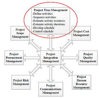
Location Based Scheduling is placed in the realm of Project Management. The main focus of the article is to describe LBS, a Project Time Management tool, used by project managers in the construction industry. As shown in Figure 2 from Project Management Body of Knowledge [3], Project Time Management is a crucial part of a project managers scope.
The overall idea with LBS is to create a schedule that can be used as followed: [4]
- The schedule should ensure that the main goal of the project is archived within the time, resource and qualitative framework applicable to the project.
- The schedule should work as an overview map of the project, showing the planned way from start to end.
- The schedule serves as a basis for analysis and decisions regarding choice of production methods, materials and supplies and other resources.
- The schedule serves as a communication tool to convey the structure of the production progress: what should be done when, which resources should be used, in which order should the tasks be carried out.
- The schedule serves as an foundation for continuous following-up on the produced part of the project. Therefore, it can be used as a basis for identifying possible deviations and the consequences of these.
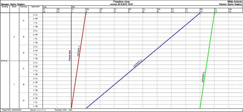
LBS is based on the fundamental planning elements: activities, resources and the link between them. In addition to this, LBS also uses -locations, critical room to manoeuvre, location based activity links and resource flow to name a few. A central part of LBS is to create the right flow through the project. The right flow ensures that the resources in the independent activities flow smoothly through the different locations of the project. A geographical location of the activities in the project is added in LBS. This makes it possible to identify where and when the different tasks should be carried out. Furthermore, it creates the possibility to draw the LBS-methods typical "Time/Place-Diagram" or "Flow-Line Diagram" (see Figure 3), which is the LBS-methods graphical representation. [4]
[edit] Flow-Line Method
Professor Shlomo Peer from Technion-Israel Inst. of Tech., Haifa, Israel, was one of the first contributors to the Flow-Line method. This method constituted a new way of displaying and handling activities in construction projects. One of Shlomo Peer's main points [5] was that scheduling and control in the construction industry should aim to complete the projects in the shortest possible time that is compatible within the financial limitations. The fastest time is not necessarily the most economical, nor is the relationship between available resources and construction time linear. Based on this statement, Shlomo Peer produced a construction planning process for the location-based methodology. The step is as follows [5]:
- Break the project down into constituent component processes.
- Divide realization of these processes between adequate production crews.
- Define technological connections between the crews and activity categories.
- Decide on the flow line that should dictate the progress of the project given financial or resource limitations.
- Estimate the resulting construction time and decide on the number of production units that should be employed in parallel.
- Balance the progress of noncritical flow lines with that of the chosen critical one, aiming to achieve working continuity.
- Within practical limits, check the possibility of shortening construction time by introducing planned breaks in continuity or changes in crew size.
- Analyse the entire process in terms of time and duration of activities and produce a plan.
When the eight steps above has been carried out, one can start producing the Flow-Line Diagram.
[edit] Flow-Line Diagram
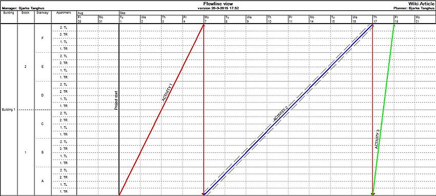
The Flow-Line Diagram is the graphic representation tool in LBS. The different activities are illustrated as lines in a XY-coordinate system. The Y-axis in the Flow-Line Diagram is divided into the physical locations of the project. The X-axis indicates the timewise progress of the project. The activities are depicted as lines in the coordinate system. The combination of axis displaying time and locations, gives an overview of where and when activities has to be carried out. The duration of each activity is seen at each location by the length of the flow-lines. The activities can be scheduled parallel to one another, so that there in this manner will be obtained an even flow and a stable rhythm of the construction. This results in, there being no days with numerous activities and other days with very few activities. The duration of each activity is estimated by the project manager in terms of man-hours needed to execute the task. The estimation is based on a combination of quantitative data in form of quantities from the tender list and qualitative experience. The actual time planned for the activity varies in proportion to the allocated resources; this is visualized by the slope of the Flow-Lines. A rapid and short activity has a steep line, while a slow and time-consuming activity has a rather flat line. In Figure 3, activity 1 and 3 have a duration of one day, and activity 2 a duration of eight days.
To create the Flow-Line Diagram, the locations of the project has to be decided.
[edit] Identifying the locations
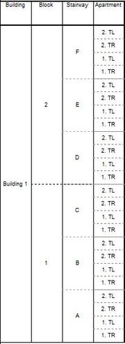
Identifying the locations of the project is a central element in the LBS-method. The projects hierarchical location structure (e.g building - block - stairway - apartment) is shown in the Flow-Line Diagram Y-axis. Each activity in the schedule is planned in relation to a location. To decide the hierarchical location structure a Location Breakdown Structure (LBS) is performed. This hierarchical breakdown structure can be compared with the Work Breakdown Structure (WBS), used in activity-based scheduling. The logic behind LBS is that the sum of locations on a lower level counterbalances a location on a higher level, as shown in Figure 4. As activities can correspond to different levels of the hierarchy, one needs to make the following considerations when determining the location hierarchy:[4]
- Which is the smallest site where repetitions will occur in the project?
- Which is the smallest locality in which material resources for current activities can be distributed?
- Which is the largest locality in which there is only room for the execution of the current activity?
E.g. preparation of the construction site would in Figure 4 corresponds to the building level in the hierarchy, whereas installation of kitchens would correspond to the apartment level in the hierarchy.
[edit] Optimization using Flow-Line Diagram
When the different locations are identified and the internal hierarchy established, then the activities can be plotted. The optimization is generated through resources and activity-links. The activity-links help reduce the length of the project, as the graphical representation in the Flow-Line Diagram secures that multiple activities can be scheduled simultaneous. This without causing an accumulation of resources at a certain location. Other traditional scheduling methods and tools, like The Gantt Chart do not ensure this visual overview when the processes "squeezes together" in the same location.
[edit] Location-Based activity-links
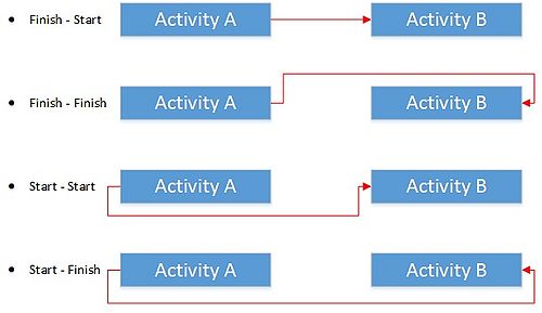
In addition to the traditional CPM-links, see Figure 5, LBS have further linkages in connection with the locations that are chosen for the schedule. These linkages is the essential in LBS. There are five different levels of location-based activity-linkages:[6]
- Activity-links between activities in the same hierarchy
- Activity-links between two activities in different hierarchies
- Internal activity-links
- Activity-links between two activities that creates a location slack
- Activity-links between two locations
| Table 1: Types of activity-links | ||
|---|---|---|
| Types of activity-links | Description | Figure |
| Traditional CPM-links | The four types of activity-links in CPM | |
| Level 1 - Activity-links between activities in the same hierarchy | Level 1 determines when an activity is to start, compared to the previous activity. The previous activity should be finished in the current location, before the next activity can begin. Figure 6 shows that Activity 2 can not start before Activity 1 is completely finished at this location. | |
| Level 2 - Activity-links between two activities in different hierarchies | Level 2 differs from level 1 as the two activities are associated with different hierarchies. It is seen from Figure 7 that Activity 1 is assigned hierarchy "Block" while Activity 2 belongs to "Apartment". A link between these activities result in Activity 2 at the earliest being able to start when Activity 1 is completely finished in the hierarchy it is affiliated with. | |
| Level 3 - Internal activity-links | Internal linkages activity is the binding location which determines the order in-house, in an activity. E.g., the order of an activity is performed, with respect to the locations of the project. Figure 8 shows that Activity 1 has an internal activity-link. First stairway A and B, then stairway D, back to stairway C, and then stairway F and E. | |
| Level 4 - Activity-links between two activities that creates a location slack | This activity-link is used when it might be necessary to create a slack between two locations. E.g., prefabricated concrete construction and outfitting. For safety reasons, there should always be a slack of at least 2 floors between installation of concrete and interior works. Figure 9 shows that Activity 2 at the earliest can begin when Activity 1 is completed on the 2nd floor of staircase A. | |
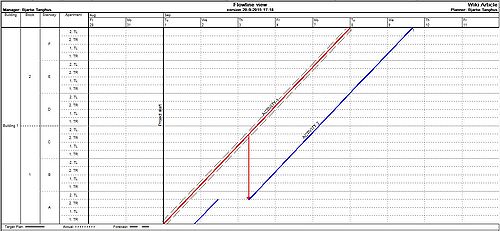
| Level 5 - Activity-links between two locations | The last level of activity-links are links that are independent of the order location. This links allows the user to select which locations to create links between. Figure 10 shows that Activity 2 can not start in stairway A - apartment 2. TL before Activity 1 is completely finished with apartment 2. TR in stairway C. This allows two alternatives for Activity 2. Either the activity can be divided so that there is a break in the activity after finishing apartment 2. TR in stairway A, as shown in Figure 10. Alternatively, the activity can start 1 day later, as shown in Figure 11, to achieve a continuous operation. | |
[edit] Control of resources and linkages
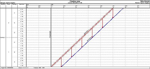
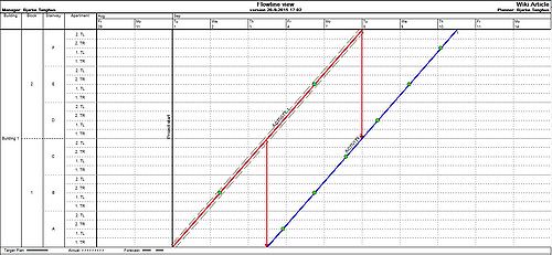
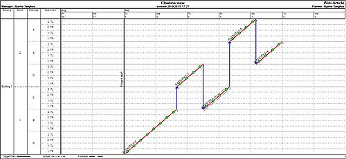
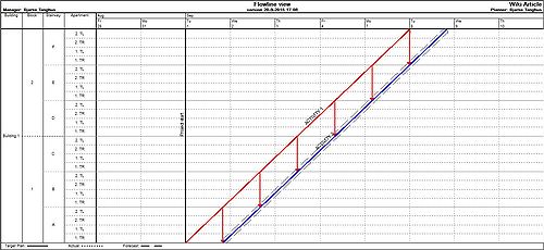
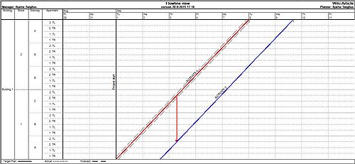
Figure 12, 13, 14 and 15 shows a schedule where three different activities are interdependent. Figure 12 shows that following activities at the earliest can start when the previous activity is fully completed - a standard "Finish-Start" CPM-link (see Table 1). Figure 13 shows another situation. Here, the following activity can start immediately after the previous activity has finished the actual location, which in this case is a stairway. Notice the difference in the length of the two schedules.
The schedule has been optimized by changing the links from standard CPM-links to LBS-links. It is possible to optimize the schedule even more, due to the overview a Flow-Line Diagram creates. Figure 13 above shows that there are multiple days where no activities are performed on some of the locations. There are two clearly unused areas in the schedule. There is an obvious big gap in Block 2 between Activity 1 and 2. Furthermore, there is a big gap between Activity 2 and 3 in Block 1.
The schedule is further optimized by:
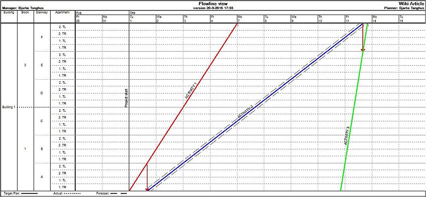
- adding resources to Activity 2 which results in a steeper slope of the Flow-Line and an earlier end date. Thereby, Activity 3 can start earlier.
- denying Activity 3 a continuous working procedure. Thereby, Activity 3 starts as soon as Activity 2 is finished with a stairway.
The two initiatives are visualized in Figure 14.
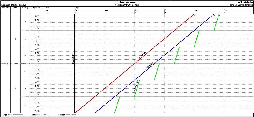
Using the Flow-Line Diagram, it is quickly determined what the most appropriate changes should be, in order to optimize the schedule. Both optimizing initiatives remove the holes in the schedule. Regulating the resources does not necessarily mean increasing staffing. By minimizing staffing in Activity 3, a similar optimization of the schedule is achieved, without the work process becoming a discontinuous operation. This is called "synchronized" [4] activities. Figure 15 illustrates this. Notice the length of the schedule is now below six days. The length of the schedule was 13 days in Figure 12.
[edit] LBS/Flow-Line Diagram compared with CPM/Gantt Chart
CPM/Gantt Chart is the most used scheduling method in Denmark. The method was developed in the late 1950s for the American Navy for planning of complex projects. It was quickly adapted by the construction industry due to its practicability in relation to construction projects. CPM only needs two types of input: the sequence of the activities and the length of them. The Gantt Chart creates a fast overview of a project but has it limitations compared to the Flow-Line Diagram. [6] [7] An example of this is showed by the two figures below:
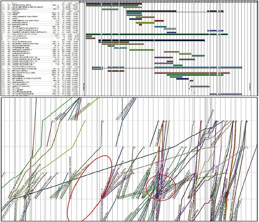
In Figure 16, the same construction project is illustrated in both a Gantt Chart and a Flow-Line Diagram. Dependencies between the activities are not shown in this example but are defined in the underlying data. Only a minor portion of the schedule is illustrated in the Gantt chart. Similar activities are typically copied and repeated for each location in a construction project, which tends to make the CPM schedules elaborate. CPM schedules commonly comprise over 1000 activities, making them difficult to manage and communicate. In the Flow-Line Diagram, similar activities are collected in tasks and displayed as a single line over multiple locations. [6] The red circles illustrates where the Flow-Line Diagram's extra input in form of locations makes a difference. The red circle on the left indicates vacant locations where no work is performed at a given time, while the red circle on the right indicates a location in which several activities are performed simultaneously. Working at the same time and in the same location negatively affects the work of construction crews because technical constraints are not respected. Logical dependencies that have to follow in succession fail. The location-based schedule illustrates areas not utilized for production (left red circle), allowing the project manager to exploit vacant areas of the build site by moving work crews to those locations. [6]
[edit] Current State of Art
Today, Location Based Scheduling is carried out by more and more contractors. Advanced software is used to create the most effective and efficient schedules possible. The advantages generated from the LBS-method gets bigger when it is combined with BIM (Building Information Modelling) tools, see BIM as a project management tool on construction projects. To minimize the numbers of errors, many projects are designed in 3D BIM today. These 3D-models are interconnected with the Location Based Schedules to create the best possible overview tool for project managers in construction. The construction sequences can be reviewed as a series of problems using 4D BIM, enabling users to explore options, manage solutions and optimize results. Furthermore, an extra dimension can be added - 5D BIM interconnects 3D models, time schedules and cost-related information to create the total overview of the construction projects. The LBS-method is applicable in all kinds of construction projects. However, it might be a more challenging task to make the right location breakdown in e.g. a bridge project than an apartment building project. [8]
[edit] Critical reflects
LBS implies a new, or preferably unfamiliar, scheduling method that requires a new approach to scheduling and it involves new ways to visualize the outcome. For example, LBS requires the definitions of locations and there are different more or less appropriate ways of dividing the project into different locations. One aspect is about finding a sufficient level of details required for the planning, scheduling and controlling of the project. It is possible, but very inconvenient, to change the level of detail once the scheduling has commenced. This reflects the classic project management challenge. The most important decisions (definitions of locations) have to be taken when the project insight is relative low. Another location difficulty could concern the definition of different kinds of locations, e.g. how to handle ground works in relation to the locations that are connected to the actual building. [8] Another disadvantage with the LBS-method is the missing exposure of the critical path. The critical path is not directly illustrated in a Flow-Line Diagram as it is in a Gantt Chart. Thus, a rule of thumb is that the slowest task in the Flow-Line Diagram is the most critical. [6]
[edit] Annotated Bibliography
References used in the Wiki-article:
- Martinez, Natalia Rodriguez (2013). Optimization of Flowline Scheduling vs.Balanced Resources and Task Continuity. Norwegian University of Science and Technology.[1]
- A study of the location-based management systems (LBMS) in construction projects. A review of the history of both the traditional (CPM, PERT) and the new methods (LBMS) set the basis of understanding for the need of changing the approach in planning.
- Sacks, R. & Partouche, R (2009). Empire State Building Project: Archetype of "Mass Construction", Journal of Construction Engineering and Management, 136(6), 702-710.[2]
- A description of how LBS was used in the construction of the Empire State Building Project.
- The Project Management Institute (2008). A Guide to the Project Management Body of Knowledge (PMBOK ® Guide), 4th Edition. PMI Publications.[3]
- Describe excellence in project management.
- Andersson, N. & Christensen, K. ‘Location-based Scheduling: "Vurdering af LBS-metodens anvendelse i byggeprojekter", The Technical University of Denmark.[4]
- This report how Location Based Scheduling (LBS) implies a shift in focus, from primarily the activities to the flow of work through the various locations of the project, i.e. the building. The report also discus how good LBS will work in the construction industry".
- Peer, S (1974) Network analysis and construction planning, Journal of the Construction Division-ASCE, 100(NCO3), p. 203–210. [5]
- The journal describes the inadequacy of network analysis and resource allocation techniques in producing a workable schedule for site management is examined in relation to the basic principles of planning the construction process.
- Büchmann-Slorup, Rolf (2012). Criticality in Location-Based Management of Construction. The Technical University of Denmark. [6]
- This PhD thesis adds to the current theory of location-based management (LBM). It describes how the different constraints in LBM affect a project’s lead time, and how the criticality of the activities changes when LBM is applied, in contrast to the prevailing techniques.
- Rezael, A. (2015). Location Based Scheduling In The Form Of Flow Line and Its Comparison to Cpm/Bar Chart Scheduling, International Journal of Electronics, Mechanical and Mechatronics Engineering, Vol.5 Num.1. p. (891-903).[7]
- This journal discuss Location-Based Scheduling compared to CPM and the Bar Chart Scheduling by use of a case study.
- Jongeling, R. & Olofsson, T (2006). A method for planning of work-flow by combined use of location-based scheduling and 4D CAD. Luleå University of Technology. [8]
- This article underline that activity-based scheduling techniques do not provide adequate support for the planning of work-flow due to practical and methodological reasons. Furthermore, it underlines that Location-based Scheduling techniques provides a promising alternative to activity-based scheduling techniques for planning of work-flow and how LBS can be used to create 4D planning.
Location-Based Scheduling Software
- The software used to create the figures of Location-Based Scheduling is TactPlan.
- Link: http://www.tactplan.com/
Videos
A short video to visualyse the benefits of Location-Based Scheduling as explained in the article.
[edit] References
- ↑ 1.0 1.1 Martinez, Natalia Rodriguez (2013). Optimization of Flowline Scheduling vs.Balanced Resources and Task Continuity. Norwegian University of Science and Technology.
- ↑ 2.0 2.1 Sacks, R. & Partouche, R (2009). Empire State Building Project: Archetype of "Mass Construction", Journal of Construction Engineering and Management, 136(6), 702-710.
- ↑ 3.0 3.1 3.2 The Project Management Institute (2008). A Guide to the Project Management Body of Knowledge (PMBOK ® Guide), 4th Edition. PMI Publications.
- ↑ 4.0 4.1 4.2 4.3 4.4 Andersson, N. & Christensen, K. ‘Location-based Scheduling: "Vurdering af LBS-metodens anvendelse i byggeprojekter", The Technical University of Denmark.
- ↑ 5.0 5.1 5.2 Peer, S (1974) Network analysis and construction planning, Journal of the Construction Division-ASCE, 100(NCO3), p. 203–210
- ↑ 6.0 6.1 6.2 6.3 6.4 6.5 6.6 Büchmann-Slorup, Rolf (2012). Criticality in Location-Based Management of Construction. The Technical University of Denmark.
- ↑ 7.0 7.1 Rezael, A. (2015). Location Based Scheduling In The Form Of Flow Line and Its Comparison to Cpm/Bar Chart Scheduling, International Journal of Electronics, Mechanical and Mechatronics Engineering, Vol.5 Num.1. p. (891-903).
- ↑ 8.0 8.1 8.2 Jongeling, R. & Olofsson, T (2006). A method for planning of work-flow by combined use of location-based scheduling and 4D CAD. Luleå University of Technology.
